Showing posts with label Distribution Transformer. Show all posts
Showing posts with label Distribution Transformer. Show all posts
FERRORESONANCE IN DISTRIBUTION TRANSFORMERS BASIC INFORMATION AND TUTORIALS
Ferroresonance is the name given to the phenomenon where the exciting reactance of the transformer can become nearly equal to the capacitive reactance of the line to ground, forming a resonant circuit. Such a resonant circuit can distort the normal line impedance to ground so that one line of a 3-phase circuit can rise to a destructive voltage.
Distribution transformers are generally considered as transformers of 500 kVA, and smaller 67,000 V and below, both single-phase and 3-phase. Older installations are primarily pole-/platform-mounted units. Newer installations are frequently pad-mounted units.
Typical applications are for supplying power to farms, residences, public buildings or stores, workshops, and shopping centers. Distribution transformers have been standardized as to high- and low-voltage ratings, taps, type of bushings, size and type of terminals, mounting arrangements, nameplates, accessories, and a number of mechanical features, so that a good degree of interchangeability results for transformers in a certain kVA range of a given voltage rating. They are now normally designed for 65 C rise.
Such a ferroresonance practically never occurs in a normal circuit configuration with the transformers loaded, but it can exist under a combination of the following circumstances which usually occur only during switching of a 3-phase bank or blowing of a fuse in one line:
1. System neutral grounded, ungrounded transformer neutral
2. No load on the transformer
3. Relatively large capacitance line-to-ground such as may exist in cable circuits (underground distribution) or very long overhead lines (although ferroresonance can be and has been corrected by adding still more capacitance which presumably throws the combination out of resonance again)
Although ferroresonance has been studied at some length, it still does not seem possible to reliably predict its occurrence. Experience indicates that it is possible to prevent ferroresonance during switching on a transformer bank if all three transformers are resistance-loaded to 15% or more of their rating, or if special switches are used to assure that the three lines close simultaneously.
SINGLE PHASE PAD MOUNTED TRANSFORMER PARTS BASIC INFORMATION AND TUTORIALS
Parts Of Pad-Mounted Single-Phase Distribution Transformers
Single-phase pad mounted distribution transformers are used in underground distribution systems where it is preferable to have underground rather than overhead distribution. An example of a single-phase, pad mounted distribution transformer with its cover raised is shown in below.
Single-phase, pad-mounted transformers are manufactured with ratings from 10 to 167 kVA. All of these distribution transformers are oil-insulated, self-cooled, and made with loop or radial feed. They can meet or exceed ANSI and NEMA standards.
Pad-mounted distribution transformers are enclosed in steel tamper-resistant protective cases designed with low profiles. They are usually painted green to blend in
Submersible single-phase distribution transformers
Single-phase submersible underground transformers are enclosed in round vertical stainless steel tanks that are hermetically sealed for protection against repeated flooding and/or immersion. The terminals, ground pads, and nameplates are mounted on the covers for easy access from ground level.
These transformers are made in ratings of 25 to 167 kVA. Where submersible transformers are to be installed in a trench that is not subject to repeated flooding or immersion, they are enclosed in stainless steel tanks. Their terminals, ground pads, and nameplates are mounted on their covers.
THREE-PHASE DISTRIBUTION TRANSFORMERS PARTS BASIC INFORMATION
WHAT ARE THE PARTS OF THREE PHASE DISTRIBUTION TRANSFORMERS (SINGLE UNIT)
A three-phase overhead distribution transformer is shown in the figure below. Where pole mounted overhead distribution is used to supply three-phase power, three-phase transformers occupy less space than a bank of transformers, and they weigh less.
Moreover, the cost of installation and maintenance is lower for a three-phase overhead transformer than for a bank of three single-phase units.
Three-phase overhead transformers are made with ratings from 30 to 300 kVA. Primary voltages range from 4.16 to 34.5 kV, and secondary voltages range from 120 to 480 V.
The basic impulse level (BIL) ratings are 45 to 150 kV. They are available with wye, delta, or T–T connections. These transformers have four output connections, X0, X1, X2, and X3, and their cases are filled with electrical-grade mineral oil.
These transformers are manufactured in ratings from 45 to 7500 kVA with high-voltage ratings from 2.4 to 46 kV. The standard connections are delta–wye, grounded wye–wye, delta–delta, wye–wye, and wye delta.
The transformers are housed in steel cabinets with front-opening, three-point latching steel doors. As in the overhead transformers, the cases of pad-mounted transformers are filled with electrical-grade mineral oil.
DISTRIBUTION TRANSFORMER TYPES BASIC AND TUTORIALS
Distribution transformers may be installed on poles, on the ground on pads, and under the ground directly or in manholes and vaults. The transformers used in these types of installations differ mainly in their packaging, as the internal operating features are very much the same.
Overhead Transformers
The overhead type of distribution transformer is mounted directly on a pole by means of two lugs, welded to the transformer tank, that engage two bolts on the pole, as shown in Figure 11-2a; this is known as direct mounting, in contrast to older methods in which the transformer was bolted to a pair of hanger irons that were hung over a cross arm.
Figure 11-2a. Direct pole mounting of a transformer (Courtesy Westinghouse Electric Co.)
Where more than one transformer is required, as in power banks, the transformer lugs engage studs on a bracket which is bolted, like a collar, around the pole; the units form a cluster around the pole, from which the term cluster mounting is derived; see Figure 11-2b.
Figure 11-2b. Cluster mounting of transformers. (Courtesy Long Island Lighting Co.)
Where the load (weight) of the transformer or transformers may be too great for the pole, they may be placed on a platform erected between two or more poles in a structure, or they may be placed on a protected ground-level pad.
Pad-Mounted Transformers
Transformers may be mounted on concrete pads at, or slightly below, ground level within an enclosure or compartment that may be locked for protection. These are generally installed as part of so-called underground residential distribution (URD) systems.
The transformers may have their energized terminals exposed when the compartment is open, or the terminals may be mounted behind an insulating barrier and connections from the cables made through bayonet-type connections on insulated elbows which are plugged into jacks connected to the terminals; these units are referred to as dead-front units and provide an additional margin of safety.
Underground Transformers
In the underground type of transformer, also called the subway type, the tank is not only hermetically sealed for water tightness, but its walls, bottom, and cover are made thicker to withstand higher internal and external pressures; the cover is bolted to the tank (with intervening gaskets) by a relatively large number of bolts, and in some instances, welding is used. These units are designed to operate completely submerged in water.
In larger units, where cooling of the tank itself is not sufficient, radiator fins are welded to the tank to provide additional cooling surface, or pipes are welded to the tank for the circulation of oil through them; in the latter case, the additional surface of the pipes as well as the circulating oil is useful for cooling.
Connections to the supply cables are made by means of watertight wiped joints between a fluid-tight bushing and the cable sheath. Another means provides for the making of connections in a chamber attached to the transformer tank in which the primary-voltage transformer windings are brought out in fluid-tight bushings.
In some units, this chamber also houses high-voltage disconnecting and grounding switches. Where these units supply low-voltage secondary networks, they also house the network protector in another watertight compartment, usually situated at the opposite end of the transformer tank from the primary connection and switch chamber.
WYE WYE CLOSED TRANSFORMER BANKING
YY CLOSED/ NEUTRAL = PRIMARY YES SECONDARY YES
How To Bank YY Close Transformers?
WHERE USED
To supply single- and three-phase loads on four-wire, multi-grounded systems. When a system has changed from delta to a four-wire wye in order to increase system capacity, existing transformers may be used (Example: Old system was 2400 volts delta; new system is 2400/4160Y volts. Existing 2400/4160Y-volt transformers may be connected in wye and used.)
YY FOR LIGHTING AND POWER
This diagram shows a system on which the primary voltage was increased from 2400 volts to 4160 volts to increase the potential capacity of the system. The previously delta-connected distribution transformers are now connected from line to neutral.
The secondaries are connected in Y. In this system, the primary neutral is connected to the neutral of the supply voltage through a metallic conductor and carried with the phase conductor to minimize telephone interference.
If the neutral of the transformer is isolated from the system neutral, an unstable condition results at the transformer neutral caused primarily by third harmonic voltages. If the transformer neutral is connected to ground, the possibility of telephone interference is greatly enhanced, and there is also a possibility of resonance between the line capacitance to ground and the magnetizing impedance of the transformer.
Dotted lines indicate transformer tanks are grounded.

CAUTION
The primary neutral should be tied firmly to the system neutral; otherwise, excessive voltages may develop on the secondary side. (5)
It is necessary that the primary neutral be available when this connection is used, and the neutrals of the primary system and of the bank are tied together as shown. If the three-phase load is unbalanced, part of the load current flows in the primary neutral.
The third-harmonic component of the transformer exciting current also flows in the primary neutral. For these reasons, it is necessary that the neutrals be tied together as shown. If this tie were omitted, the line to neutral voltages on the secondary would be very unstable.
That is, if the load on one phase were heavier than on the other two, phases would rise. Also, large third-harmonic voltages would appear between lines and neutral, both in the transformers and in the secondary system, in addition to the 60-Hz component of voltage.
This means that for a given value of RMS voltage, the peak voltage would be much higher than for a pure 60-Hz voltage. This overstresses the insulation both in the transformers and in all apparatus connected to the secondaries.
IMPEDANCE & GROUNDING
The wye-grounded/wye-grounded connection should be used only on a grounded system. It will pass ground-fault current from the primary system. Single and three-phase loads may be connected depending on the rating of the individual units, it is not necessary that the impedance of each unit in the bank be the same.
25 KVA DISTRIBUTION TRANSFORMER SPECIFICATION SAMPLE TUTORIALS
25 KVA DISTRIBUTION TRANSFORMER SPECIFICATION SAMPLE
Specification Sample of 25 KVA Distribution Transformer
Pole Mounted Amorphous Transformer Specification
Brand:
Rating: 25 kVA, Single Phase
Primary Voltage: 7620/13,200V-Y
Secondary Voltage: 120/240 Volts
BIL: 95kV
Frequency: 60 hz
Cooling Class: ONAN
Temperature Rise: 65 deg. Centigrade
No Load Loss: at most 72 watts
Load Loss: at most 411 watts
Tap Changer: +/- 2 - 2.5% above and below nominal voltage The tap changer switch shall be an externally operated
through a rotating switch.Externally accessible.
Conductor: All Aluminum conductor
Core: Amorphous Alloy
Insulation: Oil Immersed (Mineral)
Primary Connection: Eye Bolt Clamp or Plug Type
Secondary COnnection: Eye Bolt Clamp or Plug Type
Other Features: (1) Double Bushing on the Primary side, H1 & H2
(2) Secondary Bushing shall be X1,X2,X3 configuration
(3) Polarity: Additive
(4) Lifting Lugs
(5) Support Lugs
(6) Collor: Gray
TESTED & BUILT IN ACCORDANCE WITH ALL APPLICABLE ANSI STANDARDS
THREE PHASE PAD MOUNTED TRANSFORMERS BASIC AND TUTORIALS
THREE PHASE PAD MOUNTED TRANSFORMERS BASIC INFORMATION
Example Of Three Phase Pad Mounted Transformers
Three-Phase Pad-Mounted Transformers
Three-phase pad-mounted transformers are typically applied to serve commercial and industrial threephase loads from underground distribution systems. Traditionally, there have been two national standards that detailed requirements for pad-mounted transformers — one for live front (ANSI C57.12.22) and one for dead front (IEEE C57.12.26). The two standards have now been combined into one for all pad mounts, designated IEEE C57.12.34.
Live Front
Live-front transformers are specified as radial units and thus do not come with any fuse protection. See Figure 2.2.29.

The primary compartment is on the left, and the secondary compartment is on the right, with a rigid barrier separating them. The secondary door must be opened before the primary door can be opened.
Stress-cone-terminated primary cables rise vertically and connect to the terminals on the end of the high-voltage bushings. Secondary cables rise vertically and are terminated on spades connected to the secondary bushings.
Units with a secondary of 208Y/120 V are available up to 1000 kVA. Units with a secondary of 480Y/277 V are available up to 2500 kVA. Although not detailed in a national standard, there are many similar types available.
A loop-style live front (Figure 2.2.30) can be constructed by adding fuses mounted below the primary bushings. Two primary cables are then both connected to the bottom of the fuse. The loop is then made at the terminal of the high-voltage bushing, external to the transformer but within its primary compartment.

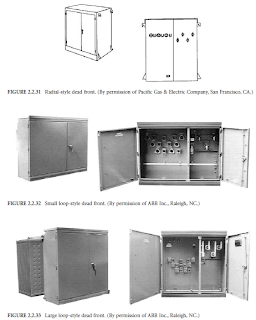
Dead Front
Both radial- and loop-feed dead-front pad-mounted transformers are detailed in the standard. Radialstyle units have three primary bushings arranged horizontally, as seen in Figure 2.2.31. Loop-style units have six primary bushings arranged in a V pattern, as seen in Figure 2.2.32 and Figure 2.2.33.
In both, the primary compartment is on the left, and the secondary compartment is on the right, with a rigid barrier between them. The secondary door must be opened before the primary door can be opened.
The primary cables are terminated with separable insulated high-voltage connectors, commonly referred to as 200-A elbows, specified in IEEE Standard 386. These plug onto the primary bushings, which can be either bushing wells with an insert, or they can be integral bushings.
Bushing wells with inserts are preferred, as they allow both the insert and elbow to be easily replaced. Units with a secondary of 208Y/ 120 V are available up to 1000 kVA. Units with a secondary of 480Y/277 V are available up to 2500 kVA.
Example Of Three Phase Pad Mounted Transformers
Three-Phase Pad-Mounted Transformers
Three-phase pad-mounted transformers are typically applied to serve commercial and industrial threephase loads from underground distribution systems. Traditionally, there have been two national standards that detailed requirements for pad-mounted transformers — one for live front (ANSI C57.12.22) and one for dead front (IEEE C57.12.26). The two standards have now been combined into one for all pad mounts, designated IEEE C57.12.34.
Live Front
Live-front transformers are specified as radial units and thus do not come with any fuse protection. See Figure 2.2.29.

The primary compartment is on the left, and the secondary compartment is on the right, with a rigid barrier separating them. The secondary door must be opened before the primary door can be opened.
Stress-cone-terminated primary cables rise vertically and connect to the terminals on the end of the high-voltage bushings. Secondary cables rise vertically and are terminated on spades connected to the secondary bushings.
Units with a secondary of 208Y/120 V are available up to 1000 kVA. Units with a secondary of 480Y/277 V are available up to 2500 kVA. Although not detailed in a national standard, there are many similar types available.
A loop-style live front (Figure 2.2.30) can be constructed by adding fuses mounted below the primary bushings. Two primary cables are then both connected to the bottom of the fuse. The loop is then made at the terminal of the high-voltage bushing, external to the transformer but within its primary compartment.

Dead Front
Both radial- and loop-feed dead-front pad-mounted transformers are detailed in the standard. Radialstyle units have three primary bushings arranged horizontally, as seen in Figure 2.2.31. Loop-style units have six primary bushings arranged in a V pattern, as seen in Figure 2.2.32 and Figure 2.2.33.
In both, the primary compartment is on the left, and the secondary compartment is on the right, with a rigid barrier between them. The secondary door must be opened before the primary door can be opened.
The primary cables are terminated with separable insulated high-voltage connectors, commonly referred to as 200-A elbows, specified in IEEE Standard 386. These plug onto the primary bushings, which can be either bushing wells with an insert, or they can be integral bushings.
Bushing wells with inserts are preferred, as they allow both the insert and elbow to be easily replaced. Units with a secondary of 208Y/ 120 V are available up to 1000 kVA. Units with a secondary of 480Y/277 V are available up to 2500 kVA.

PUBLIC RESPONSE TO TRANSFORMER AUDIBLE SOUND BASICS AND TUTORIALS
PUBLIC RESPONSE TO TRANSFORMER AUDIBLE SOUND BASIC INFORMATION
What Is The Public Response To Transformer Audible Sound?
The basic objective of a transformer noise specification is to avoid annoyance. In a particular application, the NEMA Standard level may or may not be suitable, but in order to determine whether it is, some criteria must be available.
One such criterion is that of audibility in the presence of background noise. A sound which is just barely audible should cause no complaint.
Studies of the human ear indicate that it behaves like a narrowband analyzer, comparing the energy of a single frequency tone with the total energy of the ambient sound in a critical band of frequencies centered on that of the pure tone.
If the energy in the single-frequency tone does not exceed the energy in the critical band of the ambient sound, it will not be significantly audible. This requirement should be considered separately for each of the frequencies generated by the transformer core.
The width of the ear-critical band is about 40 Hz for the principal transformer harmonics. The ambient sound energy in this band is 40 times the energy in a 1-Hz-wide band.
The sound level for a 1-Hz bandwidth is known as the “spectrum level” and is used as a reference. The sound level of the 40-Hz band is 16 dB (10 log 40) greater than the sound level of the 1-Hz band. Thus, a pure tone must be raised 16 dB above the ambient spectrum level to be barely audible.
The transformer sound should be measured at the standard NEMA positions with a narrow-band analyzer. If only the 120- and 240-Hz components are significant, an octave-band analyzer can be used, since the 75- to 150-Hz and 150- to 300-Hz octave bands each contain only one transformer frequency.
The attenuation to the position of the observer can be determined. The ambient sound should be measured at the observer’s position.
For each transformer frequency component, the ambient spectrum level should be determined. An octave band reading of ambient sound can be converted to spectrum level by the equation
S = B - 10 log C
where B = decibels octave-band reading, C = hertz octave bandwidth, and S = decibels spectrum level.
Example. Consider the following case:
Transformer sound at 120 Hz by NEMA method = 72 dB
Transformer-sound attenuation to observer = 35 dB
Ambient sound at the 75- to 150-Hz octave band = 36 dB
72 35 = 37 dB at the observer’s position
36 10 log (150 75) = 17.3-dB ambient spectrum level
The 120-Hz transformer sound at the observer’s position exceeds the ambient spectrum level by 19.7 dB. This is 3.7 dB greater than the 16-dB differential which would result in bare audibility; thus the transformer sound will be audible to the observer.
When transformer sound exceeds the limits of bare audibility, public response is not necessarily strongly negative. Some attempts have been made to categorize public response on a quantitative basis when the sound is clearly audible (Schultz and Ringlee 1960).
For a case where specific knowledge of transformer- and ambient-sound-level frequency composition is not available, some more general guidelines are useful. Typical average nighttime ambient-sound levels for certain types of communities have been established.
These are 30 dB for a “quiet suburban,” 35 dB for a “residential suburban,” and 40 dB for a “residential urban” community. All sound levels are based on the A scale of weighing.
Calculations for typical transformer frequency distributions have been made to determine the nighttime transformer noise which will be audible 50% of the time in these communities. The results are 24 dB for quiet suburban, 29 dB for residential suburban, and 34 dB for residential urban.
The NEMA standard sound level can be corrected for attenuation with distance to the nearest observer and checked against the above guides for audibility.
The broadband sound from fans, pumps, and coolers has the same character as ambient sound and tends to blend in with the ambient.
While the noise from cooling equipment may be audible to a
neighboring observer, it will seldom, if ever, cause a complaint.
DISTRIBUTION TRANSFORMERS HARMONICS AND DC EFFECTS BASIC AND TUTORIALS
DISTRIBUTION TRANSFORMERS HARMONICS AND DC EFFECTS BASIC INFORMATION
What Are The Harmonics And DC Effects Of Distribution Transformers?
Harmonics and DC Effects
Rectifier and discharge-lighting loads cause currents to flow in the distribution transformer that are not pure power-frequency sine waves. Using Fourier analysis, distorted load currents can be resolved into components that are integer multiples of the power frequency and thus are referred to as harmonics.
Distorted load currents are expected to be high in the 3rd, 5th, 7th, and sometimes the 11th and 13th harmonics, depending on the character of the load.
Odd-Ordered Harmonics
Load currents that contain the odd-numbered harmonics will increase both the eddy losses and other stray losses within a transformer. If the harmonics are substantial, then the transformer must be derated to prevent localized and general overheating.
ANSI standards suggest that any transformer with load current containing more than 5% total harmonic \ distortion should be loaded according to the appropriate ANSI guide (IEEE, 1998).
Even-Ordered Harmonics
Analysis of most harmonic currents will show very low amounts of even harmonics (2nd, 4th, 6th, etc.) Components that are even multiples of the fundamental frequency generally cause the waveform to be nonsymmetrical about the zero-current axis.
The current therefore has a zeroth harmonic or dc-offset component. The cause of a dc offset is usually found to be half-wave rectification due to a defective rectifier or other component.
The effect of a significant dc current offset is to drive the transformer core into saturation on alternate half-cycles. When the core saturates, exciting current can be extremely high, which can then burn out the primary winding in a very short time.
Transformers that are experiencing dc-offset problems are usually noticed because of objectionably loud noise coming from the core structure. Industry standards are not clear regarding the limits of dc offset on a transformer.
A recommended value is a dc current no larger than the normal exciting current, which is usually 1% or less of a winding’s rated current (Galloway, 1993).
PAD MOUNTED TRANSFORMERS SINGLE PHASE BASIC AND TUTORIALS
SINGLE PHASE PAD MOUNTED TRANSFORMERS BASIC INFORMATION
What Are Single Phase Pad Mounted Transformers?
Single-phase pad-mounted transformers are usually applied to serve residential subdivisions. Most single phase transformers are manufactured as clamshell, dead-front, loop-type with an internal 200-A primary bus designed to allow the primary to loop through and continue on to feed the next transformer.
These are detailed in the IEEE Standard C57.12.25 (ANSI, 1990). The standard assumes that the residential subdivision is served by a one-wire primary extension. It details two terminal arrangements for loopfeed systems: Type 1 (Figure 2.2.26) and Type 2 (Figure 2.2.27).
Both have two primary bushings and three secondary bushings. The primary is always on the left facing the transformer bushings with the cabinet hood open, and the secondary is on the right. There is no barrier or division between the primary and secondary.
In the Type 1 units, both primary and secondary cables rise directly up from the pad. In Type 2 units, the primary rises from the right and crosses the secondary cables that rise from the left. Type 2 units can be shorter than the Type 1 units, since the crossed cable configuration gives enough free cable length to operate the elbow without requiring the bushing to be placed as high.
Although not detailed in the national standard, there are units built with four and with six primary bushings. The four-bushing unit is used for single-phase lines, with the transformers connected phase-to-phase. The six-primary-bushing units are used to supply single-phase loads from three-phase taps.
Terminating all of the phases in the transformer allows all of the phases to be sectionalized at the same location. The internal single-phase transformer can be connected either phase-to-phase or phase-to-ground.
The six-bushing units also allow the construction of duplex pad-mounted units that can be used to supply small three-phase loads along with the normal single-phase residential load. In those cases, the service voltage is four-wire, three-phase, 120/240 V.
Cabinets for single-phase transformers are typically built in the clamshell configuration with one large door that swings up. Older units were manufactured with two doors, similar to the three-phase cabinets.
New installations are almost universally dead front; however, live-front units are still purchased for replacements. These units are also built with clamshell cabinets but have an internal box shaped insulating barrier constructed around the primary connections.
What Are Single Phase Pad Mounted Transformers?
Single-phase pad-mounted transformers are usually applied to serve residential subdivisions. Most single phase transformers are manufactured as clamshell, dead-front, loop-type with an internal 200-A primary bus designed to allow the primary to loop through and continue on to feed the next transformer.
These are detailed in the IEEE Standard C57.12.25 (ANSI, 1990). The standard assumes that the residential subdivision is served by a one-wire primary extension. It details two terminal arrangements for loopfeed systems: Type 1 (Figure 2.2.26) and Type 2 (Figure 2.2.27).
 |
| Type 1 |
 |
| Type 2 |
Both have two primary bushings and three secondary bushings. The primary is always on the left facing the transformer bushings with the cabinet hood open, and the secondary is on the right. There is no barrier or division between the primary and secondary.
In the Type 1 units, both primary and secondary cables rise directly up from the pad. In Type 2 units, the primary rises from the right and crosses the secondary cables that rise from the left. Type 2 units can be shorter than the Type 1 units, since the crossed cable configuration gives enough free cable length to operate the elbow without requiring the bushing to be placed as high.
Although not detailed in the national standard, there are units built with four and with six primary bushings. The four-bushing unit is used for single-phase lines, with the transformers connected phase-to-phase. The six-primary-bushing units are used to supply single-phase loads from three-phase taps.
Terminating all of the phases in the transformer allows all of the phases to be sectionalized at the same location. The internal single-phase transformer can be connected either phase-to-phase or phase-to-ground.
The six-bushing units also allow the construction of duplex pad-mounted units that can be used to supply small three-phase loads along with the normal single-phase residential load. In those cases, the service voltage is four-wire, three-phase, 120/240 V.
Cabinets for single-phase transformers are typically built in the clamshell configuration with one large door that swings up. Older units were manufactured with two doors, similar to the three-phase cabinets.
New installations are almost universally dead front; however, live-front units are still purchased for replacements. These units are also built with clamshell cabinets but have an internal box shaped insulating barrier constructed around the primary connections.
FERRORESONANCE AND DISTRIBUTION TRANSFORMER CONTRIBUTION BASICS AND TUTORIALS
FERRORESONANCE AND DISTRIBUTION TRANSFORMER CONTRIBUTION BASIC INFORMATION
What Is The Contribution Of Distribution Transformers On Ferroresonance?
Ferroresonance is an overvoltage phenomenon that occurs when charging current for a long underground cable or other capacitive reactance saturates the core of a transformer.
Such a resonance can result in voltages as high as five times the rated system voltage, damaging lightning arresters and other equipment and possibly even the transformer itself.
When ferroresonance is occurring, the transformer is likely to produce loud squeals and groans, and the noise has been likened to the sound of steel roofing being dragged across a concrete surface.
A typical ferroresonance situation is shown in Figure 2.2.10 and consists of long underground cables feeding a transformer with a delta-connected primary.

FIGURE 2.2.10 is a typical ferroresonance situation. (From IEEE C57.105-1978, IEEE Guide for Application of Transformer Connections in Three-Phase Distribution Systems, copyright 1978 by the Institute of Electrical and Electronics Engineers, Inc. The IEEE disclaims any responsibility or liability resulting from the placement and use in the described manner. Information is reprinted with the permission of the IEEE.)
The transformer is unloaded or very lightly loaded and switching or fusing for the circuit operates one phase at a time.
Ferroresonance can occur when energizing the transformer as the first switch is closed, or it can occur if one or more distant fuses open and the load is very light. Ferroresonance is more likely to occur on systems with higher primary voltage and has been observed even when there is no cable present.
All of the contributing factors — delta or wye connection, cable length, voltage, load, single-phase switching —must be considered together. Attempts to set precise limits for prevention of the phenomenon have been frustrating.
For more on ferroresonance click the link.
DISTRIBUTION TRANSFORMER TANK AND CABINET MATERIALS BASIC AND TUTORIALS
DISTRIBUTION TRANSFORMER TANK AND CABINET MATERIALS BASIC INFORMATION
What Are The Common Distribution Transformer Tank and Cabinet Materials?
A distribution transformer is expected to operate satisfactorily for a minimum of 30 years in an outdoor environment while extremes of loading work to weaken the insulation systems inside the transformer. This high expectation demands the best in state-of-the-art design, metal processing, and coating technologies.
Mild Steel
Almost all overhead and pad-mounted transformers have a tank and cabinet parts made from mild carbon steel. In recent years, major manufacturers have started using coatings applied by electrophoretic methods (aqueous deposition) and by powder coating.
These new methods have largely replaced the traditional flow-coating and solvent-spray application methods.
Stainless Steel
Since the mid 1960s, single-phase submersibles have almost exclusively used AISI 400-series stainless steel. These grades of stainless were selected for their good welding properties and their tendency to resist pit-corrosion.
Both 400-series and the more expensive 304L (low-carbon chromium-nickel) stainless steels have been used for pad mounts and pole types where severe environments justify the added cost.
Transformer users with severe coastal environments have observed that pad mounts show the worst corrosion damage where the cabinet sill and lower areas of the tank contact the pad. This is easily explained by the tendency for moisture, leaves, grass clippings, lawn chemicals, etc., to collect on the pad surface.
Higher areas of a tank and cabinet are warmed and dried by the operating transformer, but the lowest areas in contact with the pad remain cool. Also, the sill and tank surfaces in contact with the pad are most likely to have the paint scratched.
To address this, manufacturers sometimes offer hybrid transformers, where the cabinet sill, hood, or the tank base may be selectively made from stainless steel.
Composites
There have been many attempts to conquer the corrosion tendencies of transformers by replacing metal structures with reinforced plastics. One of the more successful is a one-piece composite hood for single phase
pad-mounted transformers.
2400 VOLTS (2.4 kV) SYSTEM AND TRANSFORMERS BASIC AND TUTORIALS
DISTRIBUTION TRANSFORMER IN THE 2.4 kV SYSTEM TUTORIALS
A Tutorial On The 2.4 kV System and Its Distribution Transformers
In any particular voltage class, the actual rated voltage of a transformer has increased in years past. For example, the 2400-volt class of transformers formerly were rated 2200-110/220, then later they were rated 2300 115/230 and today they are rated 2400-120/240 volts.
This gradual increase in the rated voltage of transformers also occurred in the other voltage classes. Throughout the following material, we will speak of a particular voltage class by using present day rated voltage terminology.

In the early days of urban-electrical distribution, practically all systems were 2400-volt class, delta systems, and the 2400-volt transformer was designed and manufactured for this system. The selection of 2400 volt for distribution was logical from the standpoint of service and economy.
This voltage is high enough to give good system performance on systems where the distribution circuits are not very long. In addition, the voltage is sufficiently low to result in economical distribution equipment.
In recent years most 2400-volt delta systems have been changed over to 2400/4160Y-volt systems. This change was due to the fact that as the 2400-volt delta systems became more heavily loaded it became necessary to put in larger distribution-line conductors or raise the operating voltage in order to maintain proper voltage regulation.
The most economical procedure in this case was to raise the operating voltage to 4160Y, and this was economical because the change did not necessitate a change in transformers or other equipment on the line.
2400/4160-volt distribution systems are used in most urban areas throughout the country. Another factor that has contributed to the change from delta to Y systems is surge protection.
The three-phase four-wire solidly grounded Y system affords good grounds for surge arresters, and therefore, this system is superior from the standpoint of surge protection.
Subscribe to:
Posts (Atom)