THREE PHASE PAD MOUNTED TRANSFORMERS BASIC INFORMATION
Example Of Three Phase Pad Mounted Transformers
Three-Phase Pad-Mounted Transformers
Three-phase pad-mounted transformers are typically applied to serve commercial and industrial threephase loads from underground distribution systems. Traditionally, there have been two national standards that detailed requirements for pad-mounted transformers — one for live front (ANSI C57.12.22) and one for dead front (IEEE C57.12.26). The two standards have now been combined into one for all pad mounts, designated IEEE C57.12.34.
Live Front
Live-front transformers are specified as radial units and thus do not come with any fuse protection. See Figure 2.2.29.
The primary compartment is on the left, and the secondary compartment is on the right, with a rigid barrier separating them. The secondary door must be opened before the primary door can be opened.
Stress-cone-terminated primary cables rise vertically and connect to the terminals on the end of the high-voltage bushings. Secondary cables rise vertically and are terminated on spades connected to the secondary bushings.
Units with a secondary of 208Y/120 V are available up to 1000 kVA. Units with a secondary of 480Y/277 V are available up to 2500 kVA. Although not detailed in a national standard, there are many similar types available.
A loop-style live front (Figure 2.2.30) can be constructed by adding fuses mounted below the primary bushings. Two primary cables are then both connected to the bottom of the fuse. The loop is then made at the terminal of the high-voltage bushing, external to the transformer but within its primary compartment.
Dead Front
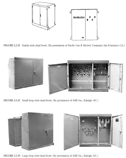
Both radial- and loop-feed dead-front pad-mounted transformers are detailed in the standard. Radialstyle units have three primary bushings arranged horizontally, as seen in Figure 2.2.31. Loop-style units have six primary bushings arranged in a V pattern, as seen in Figure 2.2.32 and Figure 2.2.33.
In both, the primary compartment is on the left, and the secondary compartment is on the right, with a rigid barrier between them. The secondary door must be opened before the primary door can be opened.
The primary cables are terminated with separable insulated high-voltage connectors, commonly referred to as 200-A elbows, specified in IEEE Standard 386. These plug onto the primary bushings, which can be either bushing wells with an insert, or they can be integral bushings.
Bushing wells with inserts are preferred, as they allow both the insert and elbow to be easily replaced. Units with a secondary of 208Y/ 120 V are available up to 1000 kVA. Units with a secondary of 480Y/277 V are available up to 2500 kVA.
POWER TRANSFORMER | DISTRIBUTION TRANSFORMER | TRANSFORMER DESIGN | TRANSFORMER PRINCIPLES | TRANSFORMER THEORY | TRANSFORMER INSTALLATION | TRANSFORMER TUTORIALS
Subscribe to:
Post Comments (Atom)
Previous Articles
-
▼
2012
(166)
-
▼
March
(23)
- TRANSFORMER INRUSH EFFECTS STUDIES DOWNLOAD LINK
- DISTRIBUTION TRANSFORMER TECHNICAL SPECIFICATION E...
- TRANSFORMER TAP CHANGER DESIGN FOR MODERATE KVA AN...
- TRANSFORMER FUSING FACTOR BASIC AND TUTORIALS
- TRANSFORMER CORE EARTHING BASICS AND TUTORIALS
- THREE PHASE PAD MOUNTED TRANSFORMERS BASIC AND TUT...
- POWER TRANSFORMERS CORE IMPROVEMENT BASIC AND TUTO...
- TRANSFORMER BUSHING STANDARDS REFERENCE BASIC AND ...
- TRANSFORMER BUSHING INSULATION TYPES BASIC AND TUT...
- PARAMETERS THAT AFFECT THE DEGRADATION OF TRANSFOR...
- HVDC REACTORS APPLICATION BASIC AND TUTORIALS
- CAPACITOR INRUSH/ OUTRUSH REACTORS BASIC AND TUTOR...
- CONSTANT VOLTAGE TRANSFORMER BASICS AND TUTORIALS
- POLARITY TEST OF SINGLE PHASE TRANSFORMER BASIC AN...
- FACTORS AFFECTING DRY TYPE TRANSFORMER'S LIFE BASI...
- ROGOWSKI COILS BASICS AND TUTORIALS
- DRY TYPE TRANSFORMERS BASICS AND TUTORIALS
- TRANSFORMER HEATING BASICS AND TUTORIALS
- PUBLIC RESPONSE TO TRANSFORMER AUDIBLE SOUND BASIC...
- POWER TRANSFORMER AUTOMATIC CONTROL FOR TAP CHANGE...
- DESIGN OF POWER TRANSFORMERS INSULATION STRUCTURES...
- POWER TRANSFORMERS IN SERVICE TESTING BASIC AND TU...
- POWER TRANSFORMER TAP CHANGERS BASIC AND TUTORIALS
-
▼
March
(23)


No comments:
Post a Comment