TRANSFORMER CORE EARTHING BASIC INFORMATION
What Is Transformer Core Earthing?
Core earthing
Before concluding the description of core construction, mention should be made of the subject of core earthing. Any conducting metal parts of a transformer, unless solidly bonded to earth, will acquire a potential in operation which depends on their location relative to the electric field within which they lie.
In theory, the designer could insulate them from earthed metal but, in practice, it is easier and more convenient to bond them to earth. However, in adopting this alternative, there are two important requirements:
ž The bonding must ensure good electrical contact and remain secure throughout the transformer life.
ž No conducting loops must be formed, otherwise circulating currents will result, creating increased losses and/or localised overheating.
Metalwork which becomes inadequately bonded, possibly due to shrinkage or vibration, creates arcing which will cause breakdown of insulation and oil and will produce gases which may lead to Buchholz relay operation, where fitted, or cause confusion of routine gas-in-oil monitoring results y masking other more serious internal faults, and can thus be very troublesome in service.
The core and its framework represent the largest bulk of metalwork requiring to be bonded to earth. On large, important transformers, connections to core and frames can be individually brought outside the tank via 3.3 kV bushings and then connected to earth externally.
This enables the earth connection to be readily accessed at the time of initial installation on site and during subsequent maintenance without lowering the oil level for removal of inspection covers so that core insulation resistance checks can be carried out.
In order to comply with the above requirement to avoid circulating currents, the core and frames will need to be effectively insulated from the tank and from each other, nevertheless it is necessary for the core to be very positively located within the tank particularly so as to avoid movement and possible damage during transport.
It is usual to incorporate location brackets within the base of the tank in order to meet this requirement. Because of the large weight of the core and windings these locating devices and the insulation between them and the core and frames will need to be physically very substantial, although the relevant test voltage may be modest.
THREE PHASE PAD MOUNTED TRANSFORMERS BASIC AND TUTORIALS
THREE PHASE PAD MOUNTED TRANSFORMERS BASIC INFORMATION
Example Of Three Phase Pad Mounted Transformers
Three-Phase Pad-Mounted Transformers
Three-phase pad-mounted transformers are typically applied to serve commercial and industrial threephase loads from underground distribution systems. Traditionally, there have been two national standards that detailed requirements for pad-mounted transformers — one for live front (ANSI C57.12.22) and one for dead front (IEEE C57.12.26). The two standards have now been combined into one for all pad mounts, designated IEEE C57.12.34.
Live Front
Live-front transformers are specified as radial units and thus do not come with any fuse protection. See Figure 2.2.29.

The primary compartment is on the left, and the secondary compartment is on the right, with a rigid barrier separating them. The secondary door must be opened before the primary door can be opened.
Stress-cone-terminated primary cables rise vertically and connect to the terminals on the end of the high-voltage bushings. Secondary cables rise vertically and are terminated on spades connected to the secondary bushings.
Units with a secondary of 208Y/120 V are available up to 1000 kVA. Units with a secondary of 480Y/277 V are available up to 2500 kVA. Although not detailed in a national standard, there are many similar types available.
A loop-style live front (Figure 2.2.30) can be constructed by adding fuses mounted below the primary bushings. Two primary cables are then both connected to the bottom of the fuse. The loop is then made at the terminal of the high-voltage bushing, external to the transformer but within its primary compartment.

Dead Front
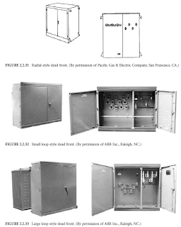
Both radial- and loop-feed dead-front pad-mounted transformers are detailed in the standard. Radialstyle units have three primary bushings arranged horizontally, as seen in Figure 2.2.31. Loop-style units have six primary bushings arranged in a V pattern, as seen in Figure 2.2.32 and Figure 2.2.33.
In both, the primary compartment is on the left, and the secondary compartment is on the right, with a rigid barrier between them. The secondary door must be opened before the primary door can be opened.
The primary cables are terminated with separable insulated high-voltage connectors, commonly referred to as 200-A elbows, specified in IEEE Standard 386. These plug onto the primary bushings, which can be either bushing wells with an insert, or they can be integral bushings.
Bushing wells with inserts are preferred, as they allow both the insert and elbow to be easily replaced. Units with a secondary of 208Y/ 120 V are available up to 1000 kVA. Units with a secondary of 480Y/277 V are available up to 2500 kVA.
Example Of Three Phase Pad Mounted Transformers
Three-Phase Pad-Mounted Transformers
Three-phase pad-mounted transformers are typically applied to serve commercial and industrial threephase loads from underground distribution systems. Traditionally, there have been two national standards that detailed requirements for pad-mounted transformers — one for live front (ANSI C57.12.22) and one for dead front (IEEE C57.12.26). The two standards have now been combined into one for all pad mounts, designated IEEE C57.12.34.
Live Front
Live-front transformers are specified as radial units and thus do not come with any fuse protection. See Figure 2.2.29.

The primary compartment is on the left, and the secondary compartment is on the right, with a rigid barrier separating them. The secondary door must be opened before the primary door can be opened.
Stress-cone-terminated primary cables rise vertically and connect to the terminals on the end of the high-voltage bushings. Secondary cables rise vertically and are terminated on spades connected to the secondary bushings.
Units with a secondary of 208Y/120 V are available up to 1000 kVA. Units with a secondary of 480Y/277 V are available up to 2500 kVA. Although not detailed in a national standard, there are many similar types available.
A loop-style live front (Figure 2.2.30) can be constructed by adding fuses mounted below the primary bushings. Two primary cables are then both connected to the bottom of the fuse. The loop is then made at the terminal of the high-voltage bushing, external to the transformer but within its primary compartment.

Dead Front
Both radial- and loop-feed dead-front pad-mounted transformers are detailed in the standard. Radialstyle units have three primary bushings arranged horizontally, as seen in Figure 2.2.31. Loop-style units have six primary bushings arranged in a V pattern, as seen in Figure 2.2.32 and Figure 2.2.33.
In both, the primary compartment is on the left, and the secondary compartment is on the right, with a rigid barrier between them. The secondary door must be opened before the primary door can be opened.
The primary cables are terminated with separable insulated high-voltage connectors, commonly referred to as 200-A elbows, specified in IEEE Standard 386. These plug onto the primary bushings, which can be either bushing wells with an insert, or they can be integral bushings.
Bushing wells with inserts are preferred, as they allow both the insert and elbow to be easily replaced. Units with a secondary of 208Y/ 120 V are available up to 1000 kVA. Units with a secondary of 480Y/277 V are available up to 2500 kVA.

Subscribe to:
Posts (Atom)