TAP CHANGERS OF POWER TRANSFORMERS BASIC INFORMATION
What Are Power Transformer Tap Changers? How Tap Changers Work?
When a transformer carries load current there is a variation in output voltage which is known as regulation. In order to compensate for this, additional turns are often made available so that the voltage ratio can be changed using a switch mechanism known as a tapchanger.
An off-circuit tapchanger can only be adjusted to switch additional turns in or out of circuit when the transformer is de-energized; it usually has between two and five tapping positions. An on-load tapchanger (OLTC) is designed to increase or decrease the voltage ratio when the load current is flowing, and the OLTC should switch the transformer load current from the tapping in operation to the neighbouring tapping without interruption.
The voltage between tapping positions (the step voltage) is normally between 0.8 per cent and 2.5 per cent of the rated voltage of the transformer. The OLTC mechanisms are based either on a slow-motion reactor principle or a high-speed resistor principle.
The former is commonly used in North America on the low-voltage winding, and the latter is normally used in Europe on the high-voltage winding.
The usual design of an OLTC in Europe employs a selector mechanism to make connection to the winding tapping contacts and a diverter mechanism to control current flows while the tapchanging takes place. The selector and diverter mechanisms may be combined or separate, depending upon the power rating.
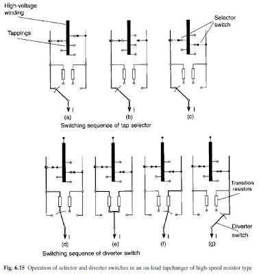
In an OLTC which comprises a diverter switch and a tap selector, the tapchange occurs in two operations. First, the next tap is selected by the tap switch but does not carry load current, then the diverter switches the load current from the tap in operation to the selected tap. The two operations are shown in seven stages in Fig. 6.15.
The tap selector operates by gearing directly from a motor drive, and at the same time a spring accumulator is tensioned. This spring operates the diverter switch in a very short time (40 – 60 ms in modern designs), independently of the motion of the motor drive.
The gearing ensures that the diverter switch operation always occurs after the tap selection has been completed. During the diverter switch operation shown in Fig. 6.15(d), (e) and (f), transition resistors are inserted; these are loaded for 20–30 ms and since they have only a short-time loading the amount of material required is very low.
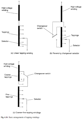
The basic arrangement of tapping windings is shown in Fig. 6.16. The linear arrangement in Fig. 6.16(a) is generally used on power transformers with moderate regulating ranges up to 20 per cent. The reversing changeover selector shown in Fig. 6.16(b) enables the voltage of the tapped winding to be added or subtracted from the main winding so that the tapping range may be doubled or the number of taps reduced.
The greatest copper losses occur at the position with the minimum number of effective turns. This reversing operation is achieved with a changeover selector which is part of the tap selector of the OLTC. The two-part coarse–fine arrangement shown in Fig. 6.16(c) may also be used.
In this case the reversing changeover selector for the fine winding can be connected to the ‘plus’ or ‘minus’ tapping of the coarse winding, and the copper losses are lowest at the position of the lowest number of effective turns. The coarse changeover switch is part of the OLTC.
Regulation is mostly carried out at the neutral point in star windings, resulting in a simple, low-cost, compact OLTC and tapping windings with low insulation strength to earth. Regulation of delta windings requires a three-phase OLTC, in which the three phases are insulated for the highest system voltage which appears between them; alternatively three single-phase OLTCs may be used.


No comments:
Post a Comment