CAPACITOR INRUSH/ OUTRUSH REACTORS BASIC INFORMATION
What Are Capacitor Inrush/ Outrush Reactors?
Capacitor switching can cause significant transients at both
the switched capacitor and remote locations.
The most common transients are:
• Overvoltage on the switched capacitor during energization
• Voltage magnification at lower-voltage capacitors
• Transformer phase-to-phase overvoltages at line
termination
• Inrush current from another capacitor during back-to-back
switching
• Current outrush from a capacitor into a nearby fault
• Dynamic overvoltage when switching a capacitor and
transformer simultaneously
Capacitor inrush/outrush reactors (Figure 2.9.15) are used
to reduce the severity of some of the transients listed above in order to
minimize dielectric stresses on breakers, capacitors, transformers, surge
arresters, and associated station electrical equipment.
High-frequency-transient interference in nearby control and
communication equipment is also reduced. Reactors are effective in reducing all
transients associated with capacitor switching, since they limit the magnitude
of the transient current (Equation 2.9.5), in kA, and significantly reduce the
transient frequency (Equation 2.9.6), in Hz.
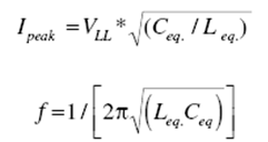
where
Ceq = equivalent capacitance of the circuit, F
Leq = equivalent inductance of the circuit, H
VLL = system line-to-line voltage, kV
Therefore, reflecting the information presented in the
preceding discussion, IEEE Std. 1036-1992, Guide for Application of Shunt Power
Capacitors, calls for the installation of reactors in series with each
capacitor bank, especially when switching back-to-back capacitor banks.

550-kV capacitor inrush/outrush reactors.
No comments:
Post a Comment