TRANSFORMER CORE DESIGN AND CONSTRUCTION BASICS AND TUTORIALS

0 comments

TRANSFORMER CORE DESIGN AND CONSTRUCTION BASIC INFORMATION
Transformer Core Design and Construction: A Tutorial 


Air gaps in a magnetic core will add considerable reluctance to the magnetic circuit. Remembering that the inductance of a coil and the magnetic reluctance are inversely proportional, air gaps reduce the inductance of the coil and increase the magnitude of magnetizing currents. In practical transformers, we want to reduce magnetizing currents to almost negligible levels; it is therefore important to eliminate all air gaps if possible.

One approach would be to make the core from a solid block of material. This is impractical from the standpoint of fabricating the transformer, since the coils would have to be wound through the core window.


Also, since metallic core materials conduct electric current as well as magnetic flux, the induced voltages would produce large circulating currents in a solid core. The circulating currents would oppose the changing flux and effectively ‘‘short out’’ the transformer.


A practical solution is to fabricate the core from thin laminated steel sheets that are stacked together and to coat the surfaces of the laminations with a thin film that electrically insulates the sheets from each other. Steel not only has excellent magnetic properties but is also relatively inexpensive and easy to fabricate into thin sheets.


In a modern transformer plant, steel ribbon is cut into sections by a cutting/punching machine commonly called a Georg machine. The sizes and shapes of the sections are determined by the core design of the individual transformer.

The thickness of the sheets varies somewhat; core laminations operating at 60 Hz are between 0.010 and 0.020 in. thick, with 0.012 in. being the most common thickness in use today.


Different methods of stacking core steel have been used in the past. One such method is called the butt lap method using rectangular core sections and is illustrated in Figure 1.11


Even if the edges of the segments do not butt together perfectly, as shown in the exaggerated edge view at the bottom of the figure, the alternating even and odd layers assure that the magnetic flux has a continuous path across the surfaces of the adjacent layers.

THE BH CURVE APPLICATION IN POWER TRANSFORMER TUTORIALS

0 comments

THE BH CURVE APPLICATION IN POWER TRANSFORMER BASIC INFORMATION
What Is BH Curve? How It Is Applied In Transformers?


For actual transformer core materials, the relationship between B and H is much more complicated. For a flux that periodically changes, the B-H curve depends on the magnitude of the flux density and the periodic
frequency.

Figure 1.7 plots the B-H curve for a ferromagnetic core with a 60 Hz sinusoidal flux density having a moderate peak value.


The B-H curve is a closed loop with the path over time moving in a counterclockwise direction over each full cycle. Note that when the magnetizing current is zero (H 0) there is still a considerable positive or negative residual flux in the core.

This residual flux is from crystalline structures in ferromagnetic materials that remain magnetically aligned even after the MMF is removed.

For a given peak amplitude of flux density, the B-H loop becomes narrower at frequencies below 60 Hz, although the width of the loop is not directly proportional to frequency. Even at very low frequencies approaching DC, the B-H curve has a finite area contained in the loop.

As seen in Figure 1.7, magnetic materials are highly nonlinear, so treating m as a constant is clearly an oversimplification. Nevertheless, assuming that materials are linear, at least over some range of flux density, is required in order to do quantitative analysis.

As the peak amplitude of the flux increases, the core goes into saturation; i.e., B increases at a much smaller rate with respect to increasing H. This means that μ gets effectively smaller as B increases. In saturation, the slope dB/dH is approximately equal to μ0. Figure 1.8 plots a typical B-H curve for a ferromagnetic core with a 60 Hz sinusoidal flux density having a large peak value.


This core material saturates at approximately +/- 1.5 Wb/m2 ( +/- 1.5 T), which is a typical saturation value for materials used in power transformers.

The magnitude of H increases greatly when the core goes into saturation, meaning that the peak magnetizing current increases dramatically. Again, the width of the B-H loop becomes narrower at frequencies below 60 Hz for a given peak amplitude of flux.

YΔ (WYE - DELTA) CLOSED / NEUTRAL = PRIM NO-SEC YES TRANSFORMER BANKING BASICS AND TUTORIALS

0 comments

WYE - DELTA TRANSFORMER BANKING TUTORIALS
Wye - Delta Primary No Secondary Yes Banking Tutorials

WHERE USED
For supplying three-phase, 240 VAC loads with small amounts of 120/240 VAC, single-phase loads. No excessive circulating currents when transformers of unequal impedance and ratio are banked. No problem from third harmonic overvoltage or telephone interference.


WYE-DELTA FOR LIGHT & POWER
This diagram shows the connections for the Y-Delta bank to supply both light and power. This connection is similar to the delta-delta bank with only the primary connections changed. The primary neutral should not be grounded or tied into the system neutral, since a single-phase ground fault may result in extensive blowing of fuses throughout the system. The single-phase load reduces the available three-phase capacity. This connection requires special watt-hour metering.


BANK RATING
The transformer with the midtap carries 2/3 of the 120/240-volt, single-phase load and 1/3 of the 240-volt, three-phase load. The other two units each carry 1/3 of both the 120/240 and 240-volt loads.

CAUTION
The secondary neutral bushing can be grounded only on one of the three transformers.

IMPEDANCE & GROUNDING
The wye-delta connection is one of the most popular connections used today. Transformers are often connected from delta-delta to wye-delta to take advantage of 1.732 times the delta transmission voltage.

In this connection, it is not necessary that the impedance of the three transformers be the same. This connection should not be used with CSP single-phase transformers since when one breaker opens; serious unbalanced secondary voltages may appear.

The wye of this system should not be grounded because then the bank serves as a grounding bank and will supply ground-fault current for a phase-to-ground fault on the primary system. Also for unbalanced three phase loads on the primary system, the secondary acts as a balance coil; therefore, circulating current may result in an overload.

STATIC DISCHARGE
Potentially present on a non-grounded primary wye connection. A high, excessive voltage results on a 3 phase Y-Δ connection on the secondary line to ground when one leg of the primary is open. The voltage present is static with no power and bleeds off when taken to ground.

This static can damage a volt-ohm meter. The static is greater when the secondary feeder is short and lesser when the secondary feeder is long. The static problem is resolved by grounding one phase or the center tap of one transformer on the secondary side, but this usually requires special KWH metering.

This static condition is present only when a primary line is open, not the secondary. This static condition can occur on an open (2-transformers) or closed (3-transformers) bank. This static condition can occur with any primary voltage.

DISTRIBUTION TRANSFORMER TANK AND CABINET MATERIALS BASIC AND TUTORIALS

0 comments

DISTRIBUTION TRANSFORMER TANK AND CABINET MATERIALS BASIC INFORMATION
What Are The Common Distribution Transformer Tank and Cabinet Materials?


A distribution transformer is expected to operate satisfactorily for a minimum of 30 years in an outdoor environment while extremes of loading work to weaken the insulation systems inside the transformer. This high expectation demands the best in state-of-the-art design, metal processing, and coating technologies.

Mild Steel
Almost all overhead and pad-mounted transformers have a tank and cabinet parts made from mild carbon steel. In recent years, major manufacturers have started using coatings applied by electrophoretic methods (aqueous deposition) and by powder coating.

These new methods have largely replaced the traditional flow-coating and solvent-spray application methods.

Stainless Steel
Since the mid 1960s, single-phase submersibles have almost exclusively used AISI 400-series stainless steel. These grades of stainless were selected for their good welding properties and their tendency to resist pit-corrosion.

Both 400-series and the more expensive 304L (low-carbon chromium-nickel) stainless steels have been used for pad mounts and pole types where severe environments justify the added cost.

Transformer users with severe coastal environments have observed that pad mounts show the worst corrosion damage where the cabinet sill and lower areas of the tank contact the pad. This is easily explained by the tendency for moisture, leaves, grass clippings, lawn chemicals, etc., to collect on the pad surface.

Higher areas of a tank and cabinet are warmed and dried by the operating transformer, but the lowest areas in contact with the pad remain cool. Also, the sill and tank surfaces in contact with the pad are most likely to have the paint scratched.

To address this, manufacturers sometimes offer hybrid transformers, where the cabinet sill, hood, or the tank base may be selectively made from stainless steel.

Composites
There have been many attempts to conquer the corrosion tendencies of transformers by replacing metal structures with reinforced plastics. One of the more successful is a one-piece composite hood for single phase
pad-mounted transformers.

DISTRIBUTION TRANSFORMER COOLANTS BASIC AND TUTORIALS

0 comments

DISTRIBUTION TRANSFORMER COOLANTS BASIC INFORMATION
What Are The Different Distribution Transformer Coolants?


Mineral Oil
Mineral oil surrounding a transformer core-coil assembly enhances the dielectric strength of the winding and prevents oxidation of the core. Dielectric improvement occurs because oil has a greater electrical withstand than air and because the dielectric constant of oil is closer to that of the insulation.

As a result, the stress on the insulation is lessened when oil replaces air in a dielectric system. Oil also picks up heat while it is in contact with the conductors and carries the heat out to the tank surface by self convection. Thus a transformer immersed in oil can have smaller electrical clearances and smaller conductors for the same voltage and kVA ratings.

Askarels
Beginning about 1932, a class of liquids called askarels or polychlorinated biphenyls (PCB) was used as a substitute for mineral oil where flammability was a major concern. Askarel-filled transformers could be placed inside or next to a building where only dry types were used previously.

Although these coolants were considered nonflammable, as used in electrical equipment they could decompose when exposed to electric arcs or fires to form hydrochloric acid and toxic furans and dioxins.
The compounds were further undesirable because of their persistence in the environment and their ability to accumulate in higher animals, including humans. Testing by the U.S. Environmental Protection

Agency has shown that PCBs can cause cancer in animals and cause other noncancer health effects. Studies in humans provide supportive evidence for potential carcinogenic and noncarcinogenic effects of PCBs (http://www.epa.gov). The use of askarels in new transformers was outlawed in 1977 (Claiborne, 1999).

Work still continues to retire and properly dispose of transformers containing askarels or askarel-contaminated mineral oil. Current ANSI/IEEE standards require transformer manufacturers to state on the nameplate that new equipment left the factory with less than 2 ppm PCBs in the oil (IEEE, 2000).

High-Temperature Hydrocarbons
Among the coolants used to take the place of askarels in distribution transformers are high-temperature hydrocarbons (HTHC), also called high-molecular-weight hydrocarbons.

These coolants are classified by the National Electric Code as “less flammable” if they have a fire point above 300˚C.

The disadvantages of HTHCs include increased cost and a diminished cooling capacity from the higher viscosity that accompanies the higher molecular weight.

TRANSFORMER ZERO SEQUENCE IMPEDANCE BASICS AND TUTORIALS

1 comments

ZERO SEQUENCE OF TRANSFORMERS BASIC INFORMATION
What Is The Zero Sequence of Transformers?


It is usual in performing system design calculations, particularly those involving unbalanced loadings and for system earth fault conditions, to use the principle of symmetrical components. This system is described and and ascribes positive, negative and zero-sequence impedance values to the components of the electrical system.

For a three-phase transformer, the positive and negative sequence impedance values are identical to that value described above, but the zero-sequence impedance varies considerably according to the construction of the transformer and the presence, or otherwise, of a delta winding.

The zero-sequence impedance of a star winding will be very high if no delta winding is present. The actual value will depend on whether there is a low reluctance return path for the third-harmonic flux.

For three-limb designs without a delta, where the return-flux path is through the air, the determining feature is usually the tank, and possibly the core support framework, where this flux creates a circulating current around the tank and/or core framework.

The impedance of such winding arrangements is likely to be in the order of 75 to 200% of the positive-sequence impedance between primary and secondary windings. For five-limb cores and three-phase banks of single-phase units, the zero-sequence impedance will be the magnetising impedance for the core configuration.

Should a delta winding exist, then the third harmonic flux will create a circulating current around the delta, and the zero-sequence impedance is determined by the leakage field between the star and the delta windings. Again the type of core will influence the magnitude of the impedance because of the effect it has on the leakage field between the windings.

Typical values for threelimb transformers having a winding configuration of core/tertiary/star LV/star HV are:

[Z0]LV approximately equal to 80 to 90% of positive-sequence impedance LV/tertiary

[Z0]HV approximately equal to 85 to 95% of positive-sequence impedance HV/tertiary

where Z0 = zero-sequence impedance.

Five-limb transformers have their zero-sequence impedances substantially equal to their positive-sequence impedance between the relative star and delta windings.

POWER TRANSFORMERS VOLTAGE REGULATION BASICS AND TUTORIALS

0 comments

VOLTAGE REGULATION OF POWER TRANSFORMERS BASICS
How To Compute The Voltage Regulation of Power Transformers?


The regulation that occurs at the secondary terminals of a transformer when a load is supplied consists, as previously mentioned, of voltage drops due to the resistance of the windings and voltage drops due to the leakage reactance between the windings. 

These two voltage drops are in quadrature with one another, the resistance drop being in phase with the load current. The percentage regulation at unity power factor load may be calculated by means of the following expression: 

(copper loss x 100/output) + [(percentage reactance) ²/200]

This value is always positive and indicates a voltage drop with load. The approximate percentage regulation for a current loading of a times rated full-load current and a power factor of cosΦ₂ is given by the following
expression: 

percent regulation = a(Vr cosΦ₂ + Vx SinΦ₂) + (a²/200) (Vx cosΦ₂ - Vr SinΦ₂)²
where VR = percentage resistance voltage at full load
                = copper loss x 100 / rated kva

At loads of low power factor the regulation becomes of serious consequence if the reactance is at all high on account of its quadrature phase relationship.

2400 VOLTS (2.4 kV) SYSTEM AND TRANSFORMERS BASIC AND TUTORIALS

0 comments

DISTRIBUTION TRANSFORMER IN THE 2.4 kV SYSTEM TUTORIALS
A Tutorial On The 2.4 kV System and Its Distribution Transformers


In any particular voltage class, the actual rated voltage of a transformer has increased in years past. For example, the 2400-volt class of transformers formerly were rated 2200-110/220, then later they were rated 2300 115/230 and today they are rated 2400-120/240 volts.

This gradual increase in the rated voltage of transformers also occurred in the other voltage classes. Throughout the following material, we will speak of a particular voltage class by using present day rated voltage terminology.


In the early days of urban-electrical distribution, practically all systems were 2400-volt class, delta systems, and the 2400-volt transformer was designed and manufactured for this system. The selection of 2400 volt for distribution was logical from the standpoint of service and economy.

This voltage is high enough to give good system performance on systems where the distribution circuits are not very long. In addition, the voltage is sufficiently low to result in economical distribution equipment.

In recent years most 2400-volt delta systems have been changed over to 2400/4160Y-volt systems. This change was due to the fact that as the 2400-volt delta systems became more heavily loaded it became necessary to put in larger distribution-line conductors or raise the operating voltage in order to maintain proper voltage regulation.

The most economical procedure in this case was to raise the operating voltage to 4160Y, and this was economical because the change did not necessitate a change in transformers or other equipment on the line.

2400/4160-volt distribution systems are used in most urban areas throughout the country. Another factor that has contributed to the change from delta to Y systems is surge protection.

The three-phase four-wire solidly grounded Y system affords good grounds for surge arresters, and therefore, this system is superior from the standpoint of surge protection.

WYE-DELTA CLOSED THREE (3) PHASE BANKING OF SINGLE PHASE TRANSFORMER TUTORIALS

0 comments

WYE - DELTA CLOSED TRANSFORMER BANKING TUTORIALS
A Tutorial On Transformer Banking (Wye -  Delta Closed)


WYE-DELTA CLOSED
YΔ CLOSED / NEUTRAL = PRIM NO-SEC NO


DIAGRAM


WHERE USED
To supply three-phase loads. No excessive circulating currents when transformers of unequal impedance and ratio are banked. No problem from third harmonic over-voltage or telephone interference. If a ground is required, it may be placed on either an X1 or an X2 bushing as shown.


WYE-DELTA FOR POWER
Often it is desirable to increase the voltage of a circuit from 2400 to 4160 volts to increase its potential capacity. This diagram shows such a system after it has been changed to 4160 volts. The previously delta-connected distribution transformer primaries are now connected from line to neutral so that no major change in equipment is necessary. The primary neutral should not be grounded or tied into the system neutral since a single-phase ground fault may result in extensive blowing of fuses throughout the system.


BANK RATING
Maximum safe bank rating for balanced three-phase loads (when transformer kva's are unequal) is three times the kva of the smallest unit. A disabled transformer renders the bank inoperative.


IMPEDANCE & GROUNDING
The wye-delta connection is one of the most popular connections used today. Transformers are often connected from delta-delta to wye-delta to take advantage of 1.732 times the delta transmission voltage.
In this connection, it is not necessary that the impedance of the three transformers be the same.
This connection should not be used with CSP single-phase transformers since when one breaker opens serious unbalanced secondary voltages may appear.

The wye of this system should not be grounded because then the bank serves as a grounding bank and will supply ground-fault current for a phase-to-ground fault on the primary system. Also for unbalanced three-phase loads on the primary system, the secondary acts as a balance coil; therefore, circulating current may result in an overload.


STATIC DISCHARGE
Potentially present on a non-grounded primary wye connection. A high, excessive voltage results on a 3-phase Y-Δ connection on the secondary line to ground when one leg of the primary is open. The voltage present is static with no power and bleeds off when taken to ground. This static can damage a volt-ohm meter.

The static is greater when the secondary feeder is short and lesser when the secondary feeder is long. The static problem is resolved by grounding one phase or the center tap of one transformer on the secondary side, but this usually requires special KWH metering. This static condition is present only when a primary line is open, not the secondary. This static condition can occur on an open (2-transformers) or closed (3-transformers) bank. This static condition can occur with any primary voltage.

FERRORESONANCE
Negative effects of ferroresonance are potentially present on non-grounded primary wye connections. There is more danger at 14,400/24.900 VAC and higher. There is more danger with smaller transformers.


A rule-of-thumb concerning negative ferroresonance effects is that transformers 25 KVA and smaller at 14,400/24,900 are susceptible to damage. 30 KVA and larger transformers are relatively safe from adverse ferroresonance effects at 14,400/24,900. Higher voltages than 14,400/24,900 would necessitate larger transformers than 30 KVA to be considered inherently safe from adverse ferroresonance effects.

On a floating Y-Δ connection, temporarily ground the primary neutral when closing or opening primary fuses to avoid adverse ferroresonance effects. A “chain ground” (a fourth or neutral cutout) should be installed and closed while closing or opening the power cutouts and then re-opened after all of the power cutouts are closed.

Configurations used to avoid ferroresonance are an open Y-Δ with a solidly grounded primary Y or a Y-Y with a solidly grounded primary and secondary Y connection.

PARALLEL OPERATION OF TRANSFORMER LOAD DISTRIBUTION TUTORIALS

0 comments

LOAD DISTRIBUTION OF TRANSFORMER DURING PARALLEL OPERATION 
How To Compute The Load Distribution of Transformer During Parallel Operation?

If parallel operated transformers have the same voltage ratio but different short circuit impedance, then the load is distributed among them in such a way that each transformer accepts a specific level of load for which the short-circuit impedance becomes the same for all the parallel operated transformers.

When none of the parallel operated transformers is permitted to be overloaded, the transformer with the minimum short-circuit impedance must operate at maximum under its rated power. Consequently, the load distribution is given by the following equation:

Example 1.8
Let us assume that three transformers operate in parallel. The first transformer has 800 kVA rated power and 4.4% short-circuit impedance. 

The rated power and the short-circuit impedance of the other two transformers is 500 kVA and 4.8%, and 315 kVA and 4.0%, respectively. 

Calculate the maximum total load of the three transformers.

Solution

From the above, it is concluded that the maximum total load (1460 kVA) represents 90.4% of the total installed power (1615 kVA).

It should be noted that, in order for the maximum total load to be equal to the total installed power, the transformers must have the same short-circuit impedance.

POWER TRANSFORMER QUESTION AND ANSWER TUTORIALS PART 1

0 comments

QUESTION AND ANSWER ABOUT POWER TRANSFORMER
Power Transformer Question and Answer

1 . What is a transformer and how does it work?

A transformer is an electrical apparatus designed to convert alternating current from one voltage to another. It can be designed to “step up” or “step down” voltages and works on the magnetic induction principle.

A transformer has no moving parts and is a completely static solid state device, which insures, under
n o rmal operating conditions, a long and t ro u b l e - f ree life. It consists, in its simplest form, of two or more coils of insulated wire wound on a laminated steel core.

When voltage is introduced to one coil, called the primary, it magnetizes the iron core . A voltage is then induced in the other coil, called the secondary or output coil. The change of voltage (or voltage ratio) between the primary and secondary depends on the turns ratio of the two coils.

2 .What are taps and when are they used?
Taps are provided on some transformers on the high voltage winding to correct for high or low voltage conditions, and still deliver full rated output voltages at the secondary terminals. Standard tap arrangements are at two-and-one -half and five percent of the rated primary voltage for both high and low voltage conditions.

For example, if the  transformer has a 480 volt primary and the available line voltage is running at 504 volts, the primary should be connected to the 5% tap above normal in order that the secondary voltage be maintained at the proper rating.

The standard ASA and NEMA designation for taps are “ANFC” (above normal full capacity) and “B N FC” (below normal full capacity).


3 . What is the difference between “ I n s u l a t i n g,” “I s o l a t i n g,” and “Shielded Winding” transformers?
Insulating and isolating transformers are identical. These terms are used to describe the isolation of the primary and secondary windings, or insulation between the two.

A shielded transformer is designed with a metallic shield between the primary and secondary windings to attenuate transient noise. This is especially important in critical applications such as computers, process controllers and many other microprocessor controlled devices.

All two, three and four winding transformers are of the insulating or isolating types. Only autotransformers ,
w hose primary and secondary are connected to each other electrically, are not of the insulating or isolating variety.

4. Can transformers be operated at voltages other than nameplate voltages?
In some cases, transformers can be operated at voltages below the nameplate rated voltage. In N O case should a transformer be operated at a voltage in excess of its nameplate rating unless taps are provided for this purpose.

When operating below the rated voltage, the K VA capacity is reduced correspondingly. For example, if a 480 volt primary transformer with a 240 volt secondary is operated at 240 volts, the secondary voltage is reduced to 120 volts.

If the transformer was originally rated 10 KVA, the reduced rating would be 5 KVA, or in direct proportion to the applied voltage.

5. Can 60 Hz transformers be operated at 50 Hz?
ACME transformers rated below 1 KVA c a n be used on 50 Hz service. Transformers 1 KVA and larger, rated at 60 Hz, should not be used on 50 Hz service due to the higher losses and resultant heat rise. Special designs are required for this service.

However, any 50 Hz transformer will operate on a 60 Hz service .

POWER TRANSFORMER SHORT CIRCUIT FORCES BASICS AND TUTORIALS

0 comments

SHORT CIRCUIT FORCES ON POWER TRANSFORMERS BASIC INFORMATION
What Are The Short Circuit Forces Acting On Power Transformers?


Forces exist between current-carrying conductors when they are in an alternating-current field. These forces are determined using :

F = B I sin x
where

F = force on conductor
B = local leakage flux density
x = angle between the leakage flux and the load current. In transformers, sin x is almost
always equal to 1.


Thus
B = uI
and therefore
F directly proportional to I^2

Since the leakage flux field is between windings and has a rather high density, the forces under shor tcircuit conditions can be quite high. This is a special area of transformer design. Complex computer programs are needed to obtain a reasonable representation of the field in different parts of the windings.

Considerable research activity has been directed toward the study of mechanical stresses in the windings and the withstand criteria for different types of conductors and support systems.

Between any two windings in a transformer, there are three possible sets of forces:

• Radial repulsion forces due to currents flowing in opposition in the two windings

• Axial repulsion forces due to currents in opposition when the electromagnetic centers of the two windings are not aligned

• Axial compression forces in each winding due to currents flowing in the same direction in adjacent
conductors

The most onerous forces are usually radial between windings. Outer windings rarely fail from hoop stress, but inner windings can suffer from one or the other of two failure modes:

• Forced buckling, where the conductor between support sticks collapses due to inward bending into the oil-duct space

• Free buckling, where the conductors bulge outwards as well as inwards at a few specific points on the circumference of the winding

Forced buckling can be prevented by ensuring that the winding is tightly wound and is adequately supported by packing it back to the core. Free buckling can be prevented by ensuring that the winding is of sufficient mechanical strength to be self-supporting, without relying on packing back to the core.

POWER TRANSFORMERS LOAD LOSSES BASICS AND TUTORIALS

0 comments

LOAD LOSSES OF POWER TRANSFORMERS BASIC INFORMATION
What Are The Load Losses Of Power Transformers?


The term load losses represents the losses in the transformer that result from the flow of load current in the windings. Load losses are composed of the following elements:

• Resistance losses as the current flows through the resistance of the conductors and leads

• Eddy losses caused by the leakage field. These are a function of the second power of the leakage field density and the second power of the conductor dimensions normal to the field.

• Stray losses: The leakage field exists in parts of the core, steel structural members, and tank walls. Losses and heating result in these steel parts.
Again, the leakage field caused by flow of the load current in the windings is involved, and the eddy and stray losses can be appreciable in large transformers. In order to reduce load loss, it is not sufficient to reduce the winding resistance by increasing the cross-section of the conductor, as eddy losses in the conductor will increase faster than joule heating losses decrease.

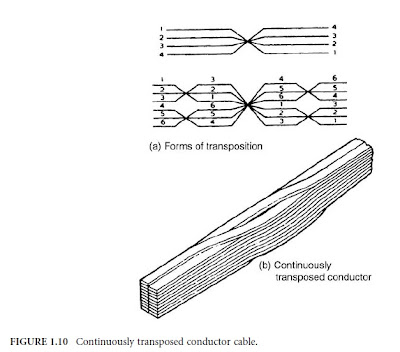
When the current is too great for a single conductor to be used for the winding without excessive eddy loss, a number of strands must be used in parallel. Because the parallel components are joined at the ends of the coil, steps must be taken to circumvent the induction of different EMFs (electromotive force) in the strands due to different loops of strands linking with the leakage flux, which would involve circulating currents and further loss.

Different forms of conductor transposition have been devised for this purpose. Ideally, each conductor element should occupy every possible position in the array of strands such that all elements have the same resistance and the same induced EMF.

Conductor transposition, however, involves some sacrifice of winding space. If the winding depth is small, one transposition halfway through the winding is sufficient; or in the case of a two-layer winding, the transposition can be located at the junction of the layers.

Windings of greater depth need three or more transpositions. An example of a continuously transposed conductor (CTC) cable, shown in Figure 1.10, is widely used in the industry. CTC cables are manufactured using transposing machines and are usually paper-insulated as part of the transposing operation.

Stray losses can be a constraint on high-reactance designs. Losses can be controlled by using a combination of magnetic shunts and/or conducting shields to channel the flow of leakage flux external to the windings into low-loss paths.

POWER TRANSFORMERS COOLING CLASSES BASICS AND TUTORIALS

1 comments

COOLING CLASSES OF POWER TRANSFORMERS BASIC INFORMATION
What Are The Cooling Classes of Power Transformers?


Since no transformer is truly an “ideal” transformer, each will incur a certain amount of energy loss, mainly that which is converted to heat. Methods of removing this heat can depend on the application, the size of the unit, and the amount of heat that needs to be dissipated.

The insulating medium inside a transformer, usually oil, serves multiple purposes, first to act as an insulator, and second to provide a good medium through which to remove the heat.

The windings and core are the primary sources of heat, although internal metallic structures can act as a heat source as well. It is imperative to have proper cooling ducts and passages in the proximity of the heat sources through which the cooling medium can flow so that the heat can be effectively removed from the transformer.

The natural circulation of oil through a transformer through convection has been referred to as a “thermosiphon” effect. The heat is carried by the insulating medium until it is transferred through the transformer tank wall to the external environment.

Radiators, typically detachable, provide an increase in the surface area available for heat transfer by convection without increasing the size of the tank. In smaller transformers, integral tubular sides or fins are used to provide this increase in surface area.

Fans can be installed to increase the volume of air moving across the cooling surfaces, thus increasing the rate of heat dissipation. Larger transformers that cannot be effectively cooled using radiators and fans rely on pumps that circulate oil through the transformer and through external heat exchangers, or coolers, which can use air or water as a secondary cooling medium.

Allowing liquid to flow through the transformer windings by natural convection is identified as “nondirected flow.” In cases where pumps are used, and even some instances where only fans and radiators are being used, the liquid is often guided into and through some or all of the windings. This is called “directed flow” in that there is some degree of control of the flow of the liquid through the windings.

The use of auxiliary equipment such as fans and pumps with coolers, called forced circulation, increases the cooling and thereby the rating of the transformer without increasing the unit’s physical size. Ratings are determined based on the temperature of the unit as it coordinates with the cooling equipment that
is operating.

Usually, a transformer will have multiple ratings corresponding to multiple stages of cooling, as the supplemental cooling equipment can be set to run only at increased loads.

Methods of cooling for liquid-immersed transformers have been arranged into cooling classes identified
by a four-letter designation as follows:
Table 2.1.2 lists the code letters that are used to make up the four-letter designation.

This system of identification has come about through standardization between different international standards organizations and represents a change from what has traditionally been used in the U.S. Where OA classified a transformer as liquid-immersed self-cooled in the past, it is now designated by the new
system as ONAN. 

Similarly, the previous FA classification is now identified as ONAF. FOA could be OFAF or ODAF, depending on whether directed oil flow is employed or not. In some cases, there are transformers with directed flow in windings without forced circulation through cooling equipment.
An example of multiple ratings would be ONAN/ONAF/ONAF, where the transformer has a base rating where it is cooled by natural convection and two supplemental ratings where groups of fans are turned on to provide additional cooling so that the transformer will be capable of supplying additional kVA. This rating would have been designated OA/FA/FA per past standards.

POWER TRANSFORMERS RATING BASICS AND TUTORIALS

0 comments

RATING OF POWER TRANSFORMERS
What Are The Basic Rating of Power Transformers?


Power Transformer Rating

In the U.S., transformers are rated based on the power output they are capable of delivering continuously at a specified rated voltage and frequency under “usual” operating conditions without exceeding prescribed internal temperature limitations.

Insulation is known to deteriorate with increases in temperature, so the insulation chosen for use in transformers is based on how long it can be expected to last by limiting the operating temperature.

The temperature that insulation is allowed to reach under operating conditions essentially determines the output rating of the transformer, called the kVA rating. Standardization has led to temperatures within a transformer being expressed in terms of the rise above ambient temperature, since the ambient temperature can vary under operating or test conditions.

Transformers are designed to limit the temperature based on the desired load, including the average temperature rise of a winding, the hottest-spot temperature rise of a winding, and, in the case of liquid-filled units, the top liquid temperature rise.

To obtain absolute temperatures from these values, simply add the ambient temperature. Standard temperature limits for liquid-immersed power transformers are listed in Table 2.1.1.
The normal life expectancy of a power transformer is generally assumed to be about 30 years of service when operated within its rating. However, under certain conditions, it may be overloaded and operated beyond its rating, with moderately predictable “loss of life.”

Situations that might involve operation beyond rating include emergency rerouting of load or through-faults prior to clearing of the fault condition.

Outside the U.S., the transformer rating may have a slightly different meaning. Based on some standards, the kVA rating can refer to the power that can be input to a transformer, the rated output being equal to the input minus the transformer losses.

Power transformers have been loosely grouped into three market segments based on size ranges. These
three segments are:

1. Small power transformers: 500 to 7500 kVA
2. Medium power transformers: 7500 to 100 MVA
3. Large power transformers: 100 MVA and above

Note that the upper range of small power and the lower range of medium power can vary between 2,500 and 10,000 kVA throughout the industry.

It was noted that the transformer rating is based on “usual” service conditions, as prescribed by standards. Unusual service conditions may be identified by those specifying a transformer so that the desired performance will correspond to the actual operating conditions.

Unusual service conditions include, but are not limited to, the following: high (above 40˚C) or low (below –20˚C) ambient temperatures, altitudes above 1000 m above sea level, seismic conditions, and loads with total harmonic distortion above 0.05 per unit.
Related Posts Plugin for WordPress, Blogger...

TOP COUNTRIES