FACTORY FIELD TEST OF POWER TRANSFORMER BASIC INFORMATION

0 comments


There are a number of field tests that are considered good predictive maintenance practices and these should be performed periodically to spot trouble. These tests are also useful for diagnosing transformer trouble.

A Megger test consists of applying a high DC voltage, usually 1000 V, to each winding with the other windings grounded and to all windings connected in parallel. The Megger readings are in megohms and these must be temperature corrected for meaningful results.

The megger readings should be compared to earlier test results to detect any downward trend in resistance values. The voltage produced by a megger is high enough to cause insulation breakdown if there are gross faults, but is really not sensitive enough to detect minor problems in transformers in the higher voltage classes.

A Doble test is somewhat more sensitive than the Megger test. An AC voltage, up to 10 kV, is applied to the winding insulation and leakage current is measured. In addition to the leakage current, the power factor of the insulation is computed.

A high power factor indicates lossy insulation, which can mean imminent trouble. In addition to the winding insulation, the Doble test is used to measure the power factor of bushing insulation. When testing condenser type bushings, the capacitance tap is utilized.

The Doble test set is also used to measure the excitation current through the winding by applying an AC voltage across the winding. High power factor readings during this test can indicate flaws in the turn-to-turn insulation.

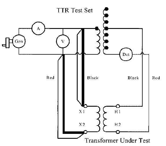
A TTR test can be used as a diagnostic test in the field. Always connect the TTR test set clamp leads to a secondary winding of the transformer under test. Connect the TTR test set clip leads to the primary winding that is on the same core leg as the secondary winding being tested, observing that the polarity of the red clip test lead matches the polarity of the red clamp test lead.

Set the ratio dials just above zero and give the generator wheel a half turn. The galvanometer should deflect to the left, indicating the ratio dials need to be raised. A deflection to the right means that the polarity of the test leads is incorrect.

This can be corrected by swapping the two clip test leads. After the correct polarity has been verified, slowly turn the generator and make the appropriate adjustments to the ratio dials in order to keep the galvanometer needle centered (zero current in the clip test leads). When the ratio dials are almost set to the right ratio, the generator can be cranked faster to get the proper voltage indication on the voltmeter (8 V).

If the voltmeter reads low voltage with the ammeter reading high current, this is usually an indication of shorted turns, either in the primary or in the secondary. A zero deflection on the galvanometer at every ratio settings indicates an open primary winding because no current can flow in the clip
test leads.

If the galvanometer deflection is always to the right and cannot be corrected by reversing the test leads, then this may indicate an open secondary winding and voltage cannot be generated in the primary winding.

RATIO TEST (TTR) OF POWER TRANSFORMER BASIC INFORMATION

1 comments


This test determines the ratio (TTR) of the number of turns in the high-voltage winding to that in the low-voltage winding. The ratio test shall be made at rated or lower voltage and rated or higher frequency.

In the case of three phase transformers when each phase is independent and accessible, single phase power should be used, although three-phase power may be used when convenient. The tolerance for the ratio test is 0.5% of the winding voltages specified on the transformer nameplate.

The accepted methods for performing the ratio test are the voltmeter method, the comparison method, and the ratio bridge. With the voltmeter method, the primary winding is excited at rated frequency and the voltage at the primary and the open-circuit voltage of the secondary winding are measured.

The ratio is the primary voltage divided by the secondary voltage. The comparison method applies voltage simultaneously to the transformer under test and the open-circuit secondary voltages are measured and compared.

The ratio bridge method is the most accurate method and can easily determine the TTR to the very small tolerances required by the standard. The test apparatus is commonly referred to as a TTR Test Set.

One such test set is manufactured by the Biddle Company and has proven to be especially useful as a diagnostic test in the field, so its operation will be described in detail. This test set is shown in Figure 8.1.

FIGURE 8.1 Circuit diagram of a TTR test set.

The clamp test leads are connected to the secondary winding of the transformer under test and the clip leads are connected to the primary winding under test. The secondary winding of the transformer under test and the secondary of a calibrated reference transformer in the test set are both excited by the same 8 V source voltage from a hand-cranked generator. A voltmeter is used to verify that the correct voltage is being applied.

An ammeter measures the exciting current into the transformer under test. When the voltage developed across the primary of the transformer under test (1-2) is equal to the voltage developed across the primary of the calibrated reference transformer (2-3), then the voltage across the synchronous rectifier is zero and the galvanometer detector reads zero.

With more voltage developed across 1-2 than across 2-3, the galvanometer has a negative deflection. With less voltage developed across 1-2 than across 2-3, the galvanometer has a positive deflection. The ratio dials are used to adjust the ratio of the reference transformer.


A simplified equivalent circuit of the TTR test set is shown in Figure 8.2. The transformer under test is also shown. Note that the current through the detector, labeled ‘‘Det’’ in the figure, is zero when the voltages developed at the high-voltage terminals of the test-set transformer and the transformer under test are equal. This condition exists when the ratios of the test-set transformer and the transformer under test are equal.

VACUUM OIL FILLING PROCEDURE TUTORIALS

0 comments


1. Remove all oil from the transformer.

2. Test new, unprocessed oil for dielectric strength using ASTM Method D877. The oil must have a minimum breakdown voltage of 30 kV.

3. After assembly, pressurize the transformer to 2 psig by adding drynitrogen. Check the transformer for leaks.

4. For transformers rated 115 kV and above, after waiting for a 24 h period, make a dew-point check to determine the dryness of the transformer insulation. For new transformers and transformers in warranty, refer to the manufacturer’s instructions for acceptable dew-point readings.

For transformers not in warranty, refer to Table 8.1.5. If it does not pass dew-point test, a hot oil dryout is required. After dryout, repeat step 4.


5. Draw a vacuum of 2 mmHg or less. Hold this vacuum for a period of time specified in the manufacturer’s instruction book, if the transformer is new or in warranty. If the transformer is not in warranty, use Table 8.1.6.


6. Maintaining a vacuum of 2 mmHg or less, admit oil into the top of the transformer connection. Once oil filling is started, it must not be interrupted. Oil degassing equipment is required for transformers rated 115 kV and above.

7. If the transformer is a conservator type, stop filling when oil reaches a level 2 in. below the transformer cover. If the transformer is equipped with a nitrogen bottle, stop filling when the oil level gauge is slightly over the 25°C level. This is to compensate for the transformer expanding when vacuum is broken and for oil cooling.

8. Break the vacuum with dry nitrogen. If the transformer has a conservator with air bag, or air separation membrane, add the remaining oil to the expansion tanks in accordance with the manufacturer’s recommendations.

9. Bleed the air from transformer oil pump vents. Turn on all pumps and leave them running while the oil cools.

10. Allow the transformer to stand before energizing (with oil pumps running) according to the timetable shown in Table 8.1.7. Run one half of the pumps for half the time and the other half of the pumps for the second half of the time.


11. Prior to energizing the transformer, check oil levels in all compartments. Pump oil into the top, if necessary, to raise the oil level to the 25°C mark.

12. Prior to energizing the transformer, shut off all oil pumps and place controls on automatic so that no pumps are running prior to energizing. This is important to eliminate static electrification of the oil, which could cause an internal failure. This hold time must be a minimum of 12 h.

POWER TRANSFORMER WINDING CONNECTION DIAGRAM

0 comments


The actual winding connections are shown in a diagram with each winding and its taps labeled. A set of tables then specifies the voltage ratings, ampere ratings, and the connections for all the available taps. For transformers with load tap changing equipment, the connection diagrams and the accompanying tables are quite extensive.

The connection diagram usually also gives the general physical layout of the transformer, showing the placement of the bushings and the locations of current transformers (CTs) and a schematic representation of the load tap changing equipment, including the preventative autotransformer, moving contacts, arcing contacts, transfer switch, and reversing switch.

A portion of an actual nameplate that shows the winding connection diagram is illustrated in Figure 7.2. The nameplate depicted is rather interesting. The transformer has a load tap changer.

From the connection diagram we see that the buried tertiary is also a tapped winding that supplies a buck/boost voltage to the secondary windings through auxiliary transformers connected between the tertiary and the secondary.

Therefore, the tertiary simultaneously provides four important functions:

1. It provides a path for third harmonic currents.
2. It helps stabilize voltages in the Y-Y primary-secondary connection.
3. It provides a grounding bank action by providing a path for zero sequence currents.
4. It provides the necessary voltage taps for regulating the low-side voltage.

The only function that the buried tertiary cannot perform is to supply an external load. The voltage rating of the buried tertiary is not given because it cannot be connected to a system voltage, but one corner of the Δ connection is grounded internally.

This grounding is done so the winding potential voltage does not ‘‘float’’ because of capacitive coupling to the other windings. Without this ground connection, capacitively induced voltages are indeterminate and could be large enough to cause insulation damage.

The voltage taps for the primary and secondary are shown on the connection diagram and on the winding rating tables in Figure 7.2. These also specify which terminal numbers and letters are connected for each tap.

This transformer has a total of 14 current transformers that are used for metering, protective relaying, and other purposes. Note the CTs marked ‘‘LDC’’ and ‘‘WDG. TEMP.’’ The term LDC stands for line drop compensation. The LDC CT supplies metered line current to a compensating device in the voltage regulator controls.

The compensating device effectively moves the voltage control point into the system connected to the secondary winding. The CT labeled WDG.TEMP supplies current to the winding temperature gauges.

These gauges use a heating element surrounding a temperature probe mounted in the top oil in order to mimic the winding temperature. The ratios of these CTs would be shown on an actual nameplate, but this information is not shown in Figure 7.2.

Just below the connection diagram is a layout sketch showing the physical locations of the bushings, the load tap changing compartment and the operating handle for the tap changer at deenergized conditions. The load tap changer is represented schematically in the connection diagram.

Note the terminals labeled P1, P2, and P3. These terminals correspond to the connections to the preventative autotransformer. The two series arcing contacts per phase that are in series with the movable contacts are shown as well.

FIGURE 7.2 Part of a transformer’s nameplate showing the voltage ratings, MVA ratings, percent impedances, connection diagram, physical layout, vector diagram, tap connections, CT connections, and BIL ratings.

POWER TRANSFORMER DESIGN VARIABLES BASICS

0 comments


Our basic design variables are:

(1) B Core flux density in Tesla
(2) Js OA current density in the secondary or LV winding in kAmps/ in2
(3)Re Core radius in inches
(4)g HV-LV gap in inches
(5)Rs Mean radius of the secondary or LV winding in inches
(6)Rp Mean radius of the primary or HV winding in inches
(7)hs Height of the secondary winding in inches
(8)ts Thickness (radial build) of the secondary winding in inches
(9)tp Thickness (radial build) of the primary winding in inches
(10)Mc Weight of the core steel in kilo-pounds
(11)Mt Weight of the tank in kilo-pounds

Note that the last two weights can be expressed in terms of the othe design variables. However, since some of the material and labor costs and losses are easily expressed in terms of them, we find it convenient to include them in the set of basic design variables.

Their dependence on the other variables will be expressed in terms of equality constraints. The units chosen for the above variables are such that their magnitudes are all in the range of about 1 to 100.

These units are used internally in the computer optimization program. As far as input and output is concerned, i.e. what the user deals with, the units are a matter of familiarity and can differ from the above.

We have not considered the height of the primary winding a design variable since, in our designs, it is usually taken to be an inch shorter then the secondary winding.

We express this as hp=αhs, where hp is the height of the primary winding and α is a fraction ≈0.95. gc and go are gaps which are fixed and inputted by the user, gc depends on whether a tertiary or tap winding is present under the LV winding and go depends on the phase to phase voltages.

H is the window height and T the window width. X is the maximum stack width ≈2Rc. These are expressible in terms of the other variables.

CURRENT TRANSFORMER (CT GROUNDING) BASIC INFORMATION

0 comments


IEEE standard C57.13.3 serves as the ANSI guide to standardize instrument transformer grounding practices. The grounding of CTs is important to both safety and the correct operation of protective relays.

To assure safe and reliable operation, the neutral of the CT secondary should have a single ground location for each circuit. The single ground is irrespective of the number of CTs or the chosen grounding location.

Utilizing a single ground eliminates the risk of redundant ground loops and associated problems.

During normal operation more than one ground on a CT circuit is not an obvious problem, other than the difficulties it may cause during testing. However, during a fault condition, multiple grounds allow a different ground potential rise for each CT.

The result is a significant current flow through the CT circuit that is not representative of the primary current. This ground loop typically creates a potential across the operating coil of the differential relay, causing the relay to pick up as though a fault exists in the relay’s protective zone.

Tripping a differential relay due to a fault external to the zone of protection is one of the more frequent nuisance trips. These nuisance trips may not only shut down the load but may require a maintenance crew to spend days testing to determine that no real problem exists in the differential zone.

Further, the actual problem may go undiscovered until the system is re-energized into the original fault.


To demonstrate what happens with a second ground on the CT circuit, refer to Figure 1. Figure 1 shows a typical differential relay with two CTs per phase. The recommended method of grounding is to install a single ground point at the first point of application (switchboard or relay panel) of the CT secondary circuit.

In the case of a fault internal to the protective zone, the voltage developed by the CTs is of the same polarity. The magnitude of voltage drop across the operating coil is sufficient to operate the relay.

A second ground is on a CT mounted near where a ground fault occurs. If the fault creates a ground potential rise of 100 volts, the protective relay will experience sufficient voltage across the operating coil to cause the relay to nuisance trip even though the fault was outside the fault zone
.
Just as with any other event, there is an exception to this standard. Many of the new multifunction relays (ABB, Schweitzer, GE/Multilin, and Basler) are designed to connect all CTs coming into the relay in a wye connection. Each wye has to be grounded.

The most desirable way to do this is to bus the wye points together at the relay panel and have a single conductor to ground to make certain the relay has but one ground potential.
Related Posts Plugin for WordPress, Blogger...

TOP COUNTRIES