CONSTANT VOLTAGE TRANSFORMER BASIC INFORMATION
What Is a Constant-Voltage Transformer?
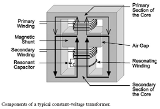
This condition occurs because of the presence of the air-gap
between the magnetic shunt and the core limbs. Air has a much higher reluctance
than the iron core.
Therefore, most of the flux passes through the lower portion
of the core, as shown by the thick lines in Figure 2.8.2.
In terms of an electrical analogy, this configuration can be
thought of as two resistances of unequal values in parallel.
The smaller resistance carries the larger current, and the
larger resistance carries the smaller current.
The CVT is designed such that:
• The lower portion of the central limb is saturated under
normal operating conditions, and the secondary and the resonating windings
operate in the nonlinear portion of the flux-current curve.
• Because of saturation in the central limb, the voltage in
the secondary winding is not linearly related to the voltage in the primary
winding.
There is consonance between the resonating winding on the
saturated core and the capacitor. This arrangement acts as a tank circuit,
drawing power from the primary. This results in sustained, regulated
oscillations at the secondary with the applied line
frequency.

No comments:
Post a Comment