PARALLEL OPERATIONS OF POWER TRANSFORMERS CONSIDERATION

0 comments


The theoretically ideal conditions for paralleling transformers are:

1. Identical turn ratios and voltage ratings.

2. Equal percent impedances.

3. Equal ratios of resistance to reactance.

4. Same polarity.

5. Same phase angle shift.

6. Same phase rotation.

Single-Phase Transformers
For single-phase transformers, only the first four conditions apply, as there is no phase rotation or phase angle shift due to voltage transformation.

If the turns ratio are not same a circulating current will flow even at no load.  If the percent impedance or the ratios of resistance to reactance are different there will be no circulating current at no load, but the division of load between the transformers when applied will no longer be proportional to their KVA ratings.

Three-Phase Transformers

The same conditions hold true for three phase transformers except that in this case the question of phase rotation and phase angle shift must be considered.

Phase Angle Shift
Certain transformer connections as the wye-delta or wye-zigzag produce a 30º shift between the line voltages on the primary side and those on the secondary side.  Transformers with these connections cannot be paralleled with other transformers not having this shift such as wye-wye, delta-delta, zigzag-delta, or zigzag-zigzag.

Phase Rotation
Phase rotation refers to the order in which the terminal voltages reach their maximum values.  In paralleling, those terminals whose voltage maximums occur simultaneously are paired.

Power Transformer Practice
The preceding discussion covered the theoretically ideal requirements for paralleling.  In actual practice, good paralleling can be accomplished although the actual transformer conditions deviate by small percentages from the theoretical ones.

Good paralleling is considered attainable when the percentage impedances of two winding transformers are within 7.5% of each other.  For multi-winding and auto-transformers, the generally accepted limit is 10%.

Furthermore, in power transformers of normal design the ratio of resistance to reactance is generally sufficiently small to make the requirement of equal ratios of negligible importance in paralleling.

When it is desired to parallel transformers having widely different impedances, reactors or auto-transformers having the proper ratio should be used.  If a reactor is used it is placed in series with the transformer whose impedance is lower.  It should have a value sufficient to bring the total effective percent impedance of the transformer plus the reactor up to the value of the percent impedance of the second transformer.

When an auto-transformer is used, the relative currents supplied by each transformer are determined by the ratio of the two sections of the auto-transformer.  The auto-transformer adds a voltage to the voltage drop in the transformer with the lower impedances and subtracts a voltage from the voltage drop in the transformer with the higher impedance.

Auto-transformers for use in paralleling power transformers are specially designed for each installation.  The wiring diagram showing the method of connecting the auto-transformer is usually furnished.

In general, transformers built to the same manufacturing specifications as indicated by the nameplate may be operated in parallel.

Connecting transformers in parallel when the low voltage tension is comparatively low requires care that the corresponding connecting bars or conductors have approximately the same impedance.  If they do not, the currents will not divide properly.

TRANSFORMER CIRCUIT MAGNETIZING REACTANCE

0 comments


For an ideal transformer, the magnetizing current is assumed to be negligible. For a real transformer, some magnetizing current must flow when voltage is applied to the winding in order to establish a flux in the core.

The voltage induced in the winding by the flux restrains the magnetizing current. It was shown earlier that the magnetizing current is not really sinusoidal, but contains many odd harmonics in addition to the fundamental frequency.

If we neglect the harmonics and concentrate on the fundamental frequency, the magnetizing current in the winding lags the applied voltage by 90°. In a two-winding transformer, this is equivalent to placing a reactance Xm, called the magnetizing reactance, in parallel with the transformer terminals.

The peak value of the magnetizing current is determined from the B-H curve of the core, which we have seen is very nonlinear. Therefore, the magnetizing reactance is not a constant but is voltage dependent; however, if the peak flux density is kept well below the point of saturation, Xm can be approximated by a constant reactance in most engineering calculations.

It is generally desirable to maximize Xm in order to minimize the magnetizing current. We saw earlier that inductance is inversely proportional to the reluctance of the core along the flux path and the reluctance of an air gap is several thousand times the reluctance of the same distance through the steel.

Therefore, even tiny air gaps in the flux path can drastically increase the core’s reluctance and decrease Xm. A proper core design must therefore eliminate all air gaps in the flux path.

Since any flux that is diverted must flow between the laminations through their surfaces, it is vital that these surfaces lie perfectly flat against each other. All ripples or waves must be eliminated by compressing the core laminations together tightly.

This also points out why the oxide layers on the lamination surfaces must be extremely thin: since these layers have essentially the same permeability as air and since the flux that is diverted from the air gaps must then travel through these oxide layers, the core’s reluctance would greatly increase if these layers were not kept extremely thin.

CONNECTING THREE-PHASE BANKS USING SINGLE-PHASE TRANSFORMERS

0 comments


There can be advantages to using single-phase transformers to make a three phase bank instead of building a three-phase unit. For instance, it may be impossible or impractical to fabricate or ship a three-phase transformer with an extremely large MVA capacity.

A bank of three single-phase transformers may then be the solution, although the total size, weight, and cost of three single-phase units will probably exceed the size, weight, and cost of one three phase unit.

An additional advantage of the bank arrangement is that a failure of one single-phase unit will usually be less costly to repair than a failure a larger three-phase unit. Furthermore, one spare single-phase transformer is usually all that is required to assure sufficient reliability for the entire bank.

With a three-phase transformer, an additional spare three-phase transformer would be required, so the total cost of the installation plus a spare transformer is twice the cost of the installation alone. The total cost of a bank of single phase transformers plus a spare is only 133% the cost of the bank alone.

Therefore, the total cost of a bank of single-phase transformers plus a spare is probably less than the cost of a three-phase transformer plus a spare.

Either Y or Δ connections are possible with single-phase transformers connected in banks. It is extremely important that the single-phase transformers are carefully matched when they are banked together, especially when the Δ connection is used.

Using mismatched transformers in the Δ connection will result in excessive circulating currents that will severely de-rate the bank or cause overheating.

One interesting configuration for a three-phase bank is the open Y-Δ connection used extensively in rural distribution systems. The open Y-Δ connection uses two single-phase transformers. An open Y-Δ connection requires only two phases plus the neutral on the primary side of the bank in order to develop a three-phase voltage at the secondary.

This is an obvious cost saving (in addition to the avoided cost of a third transformer) when the installation is far away from a three-phase primary circuit. If one of the transformers is center-tapped as then the bank provides a single-phase lighting leg in addition to a three-phase power circuit.

TRADE-OFF BETWEEN STEEL AND COPPER IN THE DESIGN OF A TRANSFORMER

0 comments


The previous section illustrated the fact that reducing a winding conductor’s length enables a corresponding reduction in the conductor’s cross-sectional area to maintain the same total I 2R losses.

Therefore, to maintain constant losses, the required volume of copper is proportional to the square of the conductor length L.

Vcu directly proportional to L^2

The required number of turns in a winding N is inversely proportional to the volts per turn generated by the core. The volts per turn are proportional to the total magnetic flux, and the flux is proportional to the cross-sectional area of the core AFe for a given allowable peak flux density, expressed as volts per turn.
N = inverselt proportional to Afe

From simple geometry, we know that the conductor’s length is equal to the number of turns times the circumference of the coil. If the cross section of the core is nearly circular and the winding is placed directly over the core, the circumference of the coil is roughly proportional to the square root of the core’s cross-sectional area.

Assuming that the core’s volume is roughly proportional to the core’s cross sectional area, The relationships given indicate that the volume of copper required to limit I 2R losses is inversely proportional to the volume of the core for a given KVA rating, winding configuration, and applied voltage.

In other words, adding 25% more core steel should permit a 25% reduction in the quantity of copper used in a transformer. This results in a 1:1 trade-off in copper volume vs. core volume.

However, that the total core losses are proportional to the core volume for a given flux density. For example, if we decide to reduce the volume of copper by 25% by increasing the volume of core steel by 25%, the core losses will increase by 25% even though the conductor losses remain constant.

In order to maintain the same core losses, the flux density must be reduced by increasing the cross-sectional area of the core, meaning that additional iron must be added. Therefore, the 1:1 trade off in copper volume vs. core volume is only a very rough approximation.

There are also other practical physical limitations in selecting the dimensions of the core and windings; however, this exercise does illustrate the kinds of trade-offs that a transformer design engineer can use to optimize economy.

THREE PHASE TRANSFORMER POLARITY EFFECTS AND STANDARD ANGULAR DISPLACEMENT BASICS AND TUTORIALS

0 comments

THREE PHASE TRANSFORMER POLARITY EFFECTS AND STANDARD ANGULAR DISPLACEMENT BASIC INFORMATION
Polarity Effects And Standard Angular Displacement Of Three Phase Transformers


Polarity Effects
Any combination of additive and subtractive units can be connected in three-phase banks so long as the correct polarity relationship of terminals is observed.

Whether a transformer is additive or subtractive does not alter the designation of the terminals (X1, X2, etc.) thus correct polarity will be assured if connections are made as indicated in the diagrams.

The terminal designations, if not marked, can be obtained from the transformer nameplate which shows the schematic internal-connection diagrams diagramming the actual physical relationship between the high and low voltage terminals.

If subtractive-polarity transformers are used in threephase banks secondary connections are simplified from those shown for the additive-polarity units.

The additivepolarity connections, for standard angular  isplacement, are somewhat complicated, particularly in cases with delta-connected secondary, by the crossed secondary interconnections between units.

For this reason simplified bank connections, which give non-standard angular displacement between primary and secondary systems, are sometimes used with additive-polarity units.

Standard Angular Displacement
Standard angular displacement or vector relationships between the primary and secondary voltage systems, as defined by ANSI publications, are 0° for delta-delta or wye-wye connected banks and 30° for delta-wye or wye-delta banks.

Angular displacement becomes important when two or more three-phase banks are interconnected into the same secondary system or when three-phase banks are paralleled. In such cases it is necessary that all of the three-phase banks have the same displacement.

The following diagrams cover three-phase circuits using:

1. Standard connections—where all units have additive polarity and give standard angular displacement or vector relation between the primary and secondary voltage systems (as defined by ANSI publications).

2. Simplified connections for the more common three phase connections with the delta-connected secondary— where all units have additive polarity but give nonstandard angular displacement between the primary and secondary voltage system.

PARTS OF TRANSFORMER OIL CONSERVATOR SYSTEM BASICS AND TUTORIALS

1 comments

PARTS OF TRANSFORMER OIL CONSERVATOR SYSTEM BASIC INFORMATION
What Are The Parts Of Transformer Oil Conservator System?


Conservators are usually mounted on one end of the transformer and well above the cover and bushings. Conservators normally have a rubber bladder inside. This bladder expands or retracts due to the temperature of the oil vs. the ambient temperature.

The inside of the bladder is connected to external piping, and then to a silica gel breather. All exposure of the oil to the air is eliminated, yet the bladder can flex.

The oil supply piping, from the conservator to the transformer, should have at least one valve. The valve(s) must be closed during the vacuum cycle as the vacuum will try to pull the rubber bladder through the piping.

The oil piping should have been cleaned prior to installation and the valves inspected. The conservator should have an inspection cover and the inside bladder inspected. While making this inspection, also check the operation of the oil float.


ADVANTAGES AND DISADVANTAGES OF THE AUTOTRANSFORMER CONNECTION TUTORIALS

0 comments

ADVANTAGES AND DISADVANTAGES OF THE AUTOTRANSFORMER CONNECTION
What Are The Advantages & Disadvantages Of Auto-transformer Connection? 


Summarizing the advantages of the autotransformer connection:

• There are considerable savings in size and weight.
• There are decreased losses for a given KVA capacity.
• Using an autotransformer connection provides an opportunity for achieving lower series impedances and better regulation.

Summarizing the disadvantages of the autotransformer connection:

• The autotransformer connection is not available with certain threephase connections.
• Higher (and possibly more damaging) short-circuit currents can result from a lower series impedance.
• Short circuits can impress voltages significantly higher than operating voltages across the windings of an autotransformer.
• For the same voltage surge at the line terminals, the impressed and induced voltages are greater for an autotransformer than for a twowinding transformer.

In many instances, the advantages of the autotransformer connection outweigh its disadvantages.

For example, when very large MVA capability is required and where a Grd.Y-Grd.Y connection is suitable, an autotransformer is usually the design of choice.

Because an autotransformer cannot provide a Δ-Y connection, autotransformers are not suitable for use as generator step-up transformers.

SUBSTATION TRANSFORMER BASICS AND TUTORIALS

0 comments

SUBSTATION TRANSFORMER BASIC INFORMATION
What Are Substation Transformer? How To Choose Substation Transformer?

Substation Transformer
Substation transformers may consist of three-phase units or banks of three single-phase units. The size of these individual installations may range from 150 kVA (three-phase) in small rural stations to upwards of 25,000 kVA at larger urban and suburban substations.


Their impedances are generally low, restricting unregulated voltage variations at the bus to a few percent, except where fault current levels are high. In this case, transformer impedances are increased to limit fault current duty to design limits.

The impedances of the transformer banks in a station should match each other as closely as practical to have the banks share the load as equally as practical.

The transformers may be connected in a delta or wye pattern, on both the incoming high-voltage (subtransmission) side and the outgoing low-voltage (primary circuit) side. The transformers are ordinarily of the two-winding standard type, operating much as the distribution transformers.

For many reasons, including the random and nonuniform movement of the molecules in the core of the transformer, the alternating magnetic field that is set up may be distorted, producing serrated sine waves on both sides of the transformer. These serrations can be broken down into a series of harmonics or waves with frequencies of 3, 5, 7, etc., times the basic frequency (usually 60 cycles per second).

If the transformers have a ground on either side, the harmonics or fluctuations flow to ground and the original sine wave essentially remains undistorted. If the windings are connected in delta fashion, these fluctuations circulate around the delta, filtering out the harmonics and eliminating them from the sine wave formed in the windings; however, they do cause some unnecessary heating.

Where the transformer windings are connected in a wye arrangement without a ground or neutral back to the source, the harmonics may be particularly bothersome. To overcome these, each of the single-phase transformations (singly or within a three-phase unit) is provided with a third, small-capacity winding; the three such windings are connected in delta (even though the main primary and secondary windings are connected in wye).

The delta thus formed allows the harmonics to circulate within it, producing a little heat but essentially filtering them out, so that the sine wave produced on both the high and low sides of the transformer will be a more pure sine wave.

PARTS OF VOLTAGE TRANSFORMERS (VT) USED IN GAS INSULATED SUBSTATION (GIS) BASICS AND TUTORIALS

0 comments

PARTS OF VOLTAGE TRANSFORMERS (VT) USED IN GAS INSULATED SUBSTATION (GIS)
What Are The Parts Of Voltage Transformers (VT) Used In GIS?


VTs are inductive types with an iron core. The primary winding is supported on an insulating plastic film immersed in SF6.


The VT should have an electric field shield between the primary and secondary windings to prevent capacitive coupling of transient voltages.

The VT is usually a sealed unit with a gas barrier insulator. The VT is either easily removable so the GIS can be high voltage tested without damaging the VT, or the VT is provided with a disconnect switch or removable link

PARTS OF CURRENT TRANSFORMERS (CT) USED IN GAS INSULATED SUBSTATION (GIS) BASICS AND TUTORIALS

0 comments

PARTS OF CURRENT TRANSFORMERS (CT) USED IN GAS INSULATED SUBSTATION (GIS)
What Are The Parts Of Current Transformers (CT) Used In GIS?


CTs are inductive ring types installed either inside the GIS enclosure or outside the GIS enclosure. The GIS conductor is the single turn primary for the CT.


CTs inside the enclosure must be shielded from the electric field produced by the high voltage conductor or high transient voltages can appear on the secondary through capacitive coupling.


For CTs outside the enclosure, the enclosure itself must be provided with an insulating joint, and enclosure currents shunted around the CT.

Both types of construction are in wide use.

WYE - DELTA OPEN TRANSFORMER BANKING BASICS AND TUTORIALS

0 comments

WYE - DELTA OPEN TRANSFORMER BANKING BASIC INFORMATION
How To Bank Wye-Delta Open Transformer?


WHERE USED
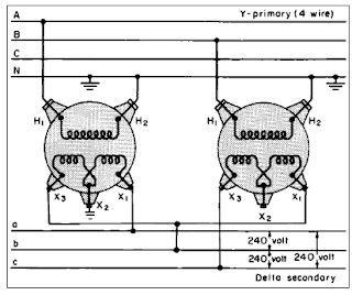
To supply large single-phase, 240-volt loads with small amounts of three-phase loads. (Usually transformers of different kva sizes are used.) Also used for emergency operation when one unit of a four-wire primary, wye-delta bank is disabled. If a ground is required, it may be placed on an X1 or an X2 bushing as shown.

OPEN Y-DELTA
When operating Y-delta and one phase is disabled, service may be maintained at reduced load as shown. The neutral in this case must be connected to the neutral of the step-up bank though a copper conductor.

The system is unbalanced, electro-statically and electro-magnetically, so that telephone interference may be expected if the neutral is connected to ground. The useful capacity of the open Y-delta bank is 87 percent of the capacity of the installed transformers when the two units are identical. The capacity is 57 percent of a three transformer bank.


BANK RATING
This connection is relatively inefficient where three-phase loads predominate since it has only 86.6% of the rating of the two units making up the three-phase bank. It also has only 57.7 % of the three-phase rating of a closed delta-delta bank of three units.

STATIC DISCHARGE
Potentially present on a non-grounded primary wye connection. A high, excessive voltage results on a 3-phase Y-Δ connection on the secondary line to ground when one leg of the primary is open.

The voltage present is static with no power and bleeds off when taken to ground. This static can damage a volt-ohm meter. The static is greater when the secondary feeder is short and lesser when the secondary feeder is long.

The static problem is resolved by grounding one phase or the center tap of one transformer on the secondary side, but this usually requires special KWH metering. This static condition is present only when a primary line is open, not the secondary.

This static condition can occur on an open (2-transformers) or closed (3-transformers) bank. This static condition can occur with any primary voltage.

WYE WYE CLOSED TRANSFORMER BANKING

0 comments

YY CLOSED/ NEUTRAL = PRIMARY YES SECONDARY YES
How To Bank YY Close Transformers?


WHERE USED
To supply single- and three-phase loads on four-wire, multi-grounded systems. When a system has changed from delta to a four-wire wye in order to increase system capacity, existing transformers may be used (Example: Old system was 2400 volts delta; new system is 2400/4160Y volts. Existing 2400/4160Y-volt transformers may be connected in wye and used.)


YY FOR LIGHTING AND POWER
This diagram shows a system on which the primary voltage was increased from 2400 volts to 4160 volts to increase the potential capacity of the system. The previously delta-connected distribution transformers are now connected from line to neutral.

The secondaries are connected in Y. In this system, the primary neutral is connected to the neutral of the supply voltage through a metallic conductor and carried with the phase conductor to minimize telephone interference.

If the neutral of the transformer is isolated from the system neutral, an unstable condition results at the transformer neutral caused primarily by third harmonic voltages. If the transformer neutral is connected to ground, the possibility of telephone interference is greatly enhanced, and there is also a possibility of resonance between the line capacitance to ground and the magnetizing impedance of the transformer.

Dotted lines indicate transformer tanks are grounded.


CAUTION
The primary neutral should be tied firmly to the system neutral; otherwise, excessive voltages may develop on the secondary side. (5)

It is necessary that the primary neutral be available when this connection is used, and the neutrals of the primary system and of the bank are tied together as shown. If the three-phase load is unbalanced, part of the load current flows in the primary neutral.

The third-harmonic component of the transformer exciting current also flows in the primary neutral. For these reasons, it is necessary that the neutrals be tied together as shown. If this tie were omitted, the line to neutral voltages on the secondary would be very unstable.

That is, if the load on one phase were heavier than on the other two, phases would rise. Also, large third-harmonic voltages would appear between lines and neutral, both in the transformers and in the secondary system, in addition to the 60-Hz component of voltage.

This means that for a given value of RMS voltage, the peak voltage would be much higher than for a pure 60-Hz voltage. This overstresses the insulation both in the transformers and in all apparatus connected to the secondaries.


IMPEDANCE & GROUNDING
The wye-grounded/wye-grounded connection should be used only on a grounded system. It will pass ground-fault current from the primary system. Single and three-phase loads may be connected depending on the rating of the individual units, it is not necessary that the impedance of each unit in the bank be the same.


TRANSFORMER NO LOAD LOSSES BASICS AND TUTORIALS

0 comments

TRANSFORMER NO LOAD LOSSES BASIC INFORMATION
What Are The Transformer No Load Losses?


Alternating magnetic flux produces both hysteresis losses and eddy-current losses in the steel. As we have seen, hysteresis losses depend on several factors including the frequency, the peak flux density, the type of core steel used, and the orientation of the flux with respect to the ‘‘grain’’ of the steel.

All of the above factors, except the frequency, are under the control of the transformer designer. Core losses are sometimes referred to as iron losses and are commonly referred to as no load losses, because core losses do not require load currents.

Decreasing the induced voltage per turn can reduce the peak flux density. This obviously involves increasing the numbers of turns in both the primary and secondary windings in order to maintain the same transformer turns ratio.

The disadvantage of adding more turns is that this increases the length of conductor and increases the conductor resistance. More cross sectional area is required in order to keep the resistance constant.

Doubling the number of turns requires about four times the volume of copper. Another way of reducing core losses is to use various types of low-loss core steels that are now available, including ‘‘amorphous’’ core materials, which have extremely low losses and superior magnetic properties.

Unfortunately, amorphous core materials have ceramic-like properties, so fabricating transformer cores with these materials is much more difficult than with laminated steel cores.

With grain-oriented steel, the direction of the core flux must be kept more or less parallel to the grain of the steel by mitering the corners of the laminations where the flux changes direction by 90°. Since the flux will cross the grain at about a 45° angle at the mitered edges, the hysteresis losses will increase somewhat in these places.

These additional localized core losses must be factored into the calculation of the total core losses. Building up the core with thin laminated strips controls eddy losses in the core, each strip having an oxide film applied to the surface.

The oxide film is extremely thin and it is more like a high-resistance film than true electrical insulation; but since the potential differences between adjacent laminations is quite small, the resistance of the oxide film is very effective in breaking up the eddy current paths.

During the manufacture of the core, the core cutting machine must not be allowed to get dull; otherwise, ‘‘burrs’’ will form along the edges of the laminations. Burrs are imperfections that form electrical bridges between the laminations and create paths for eddy currents and increased losses.

Sometimes the eddy currents near a burr can be large enough to cause localized overheating that can actually cause core damage. Core losses are approximately proportional to the square of the excitation voltage E applied to the transformer.

Therefore, placing an equivalent linear conductance Gm across the transformer terminals can approximate transformer core losses. The core losses are expressed by Wm = E^2Gm

ISOLATION TRANSFORMER BASICS AND TUTORIALS

0 comments

ISOLATION TRANSFORMER BASIC INFORMATION
What Are Isolation Transformers? How Isolation Transformer Works?


When servicing any electronic equipment, always use an isolation transformer to protect yourself from an electrical shock. During servicing, the isolation transformer is connected between the equipment and AC power line.

An isolation transformer is a transformer that has a 1:1turn ratio to provide the standard line voltage at the secondary outlet.

This means that it does not change the voltage. The transformer still produces 240 V AC as is outputs, but both sides of this AC lines are independent of ground.

If you were to accidentally touch one of these outputs, you would be protected. The isolation transformer must be rated to handle the power of any equipment connected to it. Typical ratings are 250 to 500 W.

Variable transformer or variacs is not an isolation transformer.

25 KVA DISTRIBUTION TRANSFORMER SPECIFICATION SAMPLE TUTORIALS

0 comments

25 KVA DISTRIBUTION TRANSFORMER SPECIFICATION SAMPLE
Specification Sample of 25 KVA Distribution Transformer


Pole Mounted Amorphous Transformer Specification

Brand:
Rating: 25 kVA, Single Phase
Primary Voltage: 7620/13,200V-Y
Secondary Voltage: 120/240 Volts
BIL: 95kV
Frequency: 60 hz
Cooling Class: ONAN
Temperature Rise: 65 deg. Centigrade
No Load Loss: at most 72 watts
Load Loss: at most 411 watts
Tap Changer: +/- 2 - 2.5% above and below nominal voltage The tap changer switch shall be an externally operated
through a rotating switch.Externally accessible.
Conductor: All Aluminum conductor
Core: Amorphous Alloy
Insulation: Oil Immersed (Mineral)
Primary Connection: Eye Bolt Clamp or Plug Type
Secondary COnnection: Eye Bolt Clamp or Plug Type
Other Features: (1) Double Bushing on the Primary side, H1 & H2
(2) Secondary Bushing shall be X1,X2,X3 configuration
(3) Polarity: Additive
(4) Lifting Lugs
(5) Support Lugs
(6) Collor: Gray


TESTED & BUILT IN ACCORDANCE WITH ALL APPLICABLE ANSI STANDARDS

69 kV VOLTAGE TRANSFORMER SPECIFICATION EXAMPLE TUTORIALS

0 comments

69 kV VOLTAGE TRANSFORMER SPECIFICATION EXAMPLE 
Specification Example of 69 kV Voltage Transformer


VOLTAGE TRANSFORMER

Brand:
Rated Voltage (kV): 72.5kV
Rated Frequency (Hz): 60
Type:         EMFC 84
Design:         Outdoor
Basic Insulation Level (kV) : 350kV
Rated primary voltage and ratio 69,000 Grd Y/40,250
Ratio: 350/600 & 350/600:1
Accuracy Class at Standard Burden: 0.3
Thermal Burden Rating: 200 VA @ 300 ambient

15 kV VOLTAGE TRANSFORMER SPECIFICATION SAMPLE TUTORIALS

1 comments

15 kV VOLTAGE TRANSFORMER SPECIFICATION SAMPLE 
Specification Sample of 15 kV Voltage Transformer


VOLTAGE TRANSFORMER

Brand:
Rated Voltage (kV): 15kV 15kV
Rated Frequency (Hz): 60 60
Type: VEF 24-03 (Single Bushing) VRM-24
Design: Outdoor Outdoor
Basic Insulation Level (kV) : 125 kV 125 kV
Rated primary voltage and ratio 8,400 for 14,400Y (8,400:120) 8,400 for 14,400Y (8,400:120)
Ratio: 70:1 70:1
Accuracy Class at Standard Burden: 0.3 W, X 0.3 W, X
Thermal Burden Rating: 690 VA @ 300 ambient Temp. 690 VA @ 300 ambient Temp.

69 kV COMBINED VOLTAGE AND CURRENT TRANSFORMER SPECIFICATION EXAMPLE TUTORIALS

0 comments

69 kV COMBINED VOLTAGE AND CURRENT TRANSFORMER SPECIFICATION EXAMPLE
Specification Sample Of Voltage-Current Transformer (69 kV)


Description:
Combined CT-VT consists of a current transformer portion located at the top of the unit and a voltage transformer portion in a tank at the base. External insulation consists of a one piece post type insulator.  All external parts are of corrosion – resistant material. The combined CT–VT shall be hermetically sealed.

For Oil-Filled Type:
The unit shall be hermetically sealed and of the minimum oil-filed type and compact design. All sealing shall be located below the oil level. The expansion room shall be of a gas cushion type filled with nitrogen. Oil level should be of the reflection type and without moving parts. Primary terminals shall be suitable for connection of copper or aluminum connectors. The external ferrous parts shall be of hair pin type insulation consisting of oil-impregnated paper and capacitor layers for voltage grading. It should be preferably provided with a capacitance voltage tap through out thru an insulated, factory grounded, bushing for checking the condition of its primary insulation. It should have a high seismic withstand capability of 0.5G. The unit must be able to be tilted to 60 deg. C.

For Gas Type:
The primary and secondary winding of the SF6 Gas Insulated shall be housed in a non-corrosive cylinder hermetically sealed type, preventing any contact of the SF6 with the atmosphere by means of separate flexible diaphragm.

The instrument transformer shall have the following built-in devices:
A Pressure Relief Device that is set to trigger at the designed over-pressure value.
An SF6 Gas Pressure Indicator with pressure graduations showing the Normal and High/Low danger levels of SF6 Gas Pressure.
Pressure switches with two (2) sets of NO/NC contacts for  connection with the Substation Alarm/Protection Circuits.
   - One (1) sets of contacts calibrated to trigger at Low Pressure Alarm
     Level.
- One (1) sets of contacts calibrated to trigger at Low Pressure Danger
  Level.
Type Outdoor Type, Minimum Oil-filled or Gas Insulated
Cooling Oil-immersed/ Gas insulated, self-cooled
Model Combined VT/CT
Construction Single phase, inductive type, single bushing
Termination Line-to-ground
Accuracy Class 0.3 or better thru burden W up to Y for both cores for VT, Extended Accuracy Range
0.3 or better thru B-0.1 up to B-1 for  both cores for CT
Compliance to Standard ANSI/IEEE C57.13 or applicable IEC
Nominal System Voltage, KV 69
Maximum Continuous System Voltage, KV 72.5
BIL 350 KV, 60 Hz
Minimum Creepage Distance 1380 mm
Number of Core for VT Two (2)
Single Ratio (L-G) 40250V : 115V
PTR 350 : 1
Rated Secondary Voltage 115V
Number of Core for CT Two (2)
Rating Factor 1.5 at 30oC
Accuracy Range 1% up to 150 %
CTR (Double Ratio) (To be computed based on the actual load)
Rated Secondary Current 5 A
Rated withstand and test voltage, KV
Low frequency withstand, KV RMS
Impulse  lightning  withstand, KV crest

140

325
Short Time Rating Current (per IEC)
1. Thermal Ith, KA
2. Dynamic, Idyn, KA
22
55
Mounting Pedestal
Rated Frequency, Hz 60
Post Insulator Characteristics
1. Voltage Class, KV
2. Color
3. Creepage Length, mm
72.5
Chocolate brown (preferred)
1380

Accessories
1-set Primary Connectors, clamp type terminal of nickel-plated brass for horizontal connection of round aluminum or copper conductors.
Secondary Connectors, 1 set- M10 split studs with 3.2 mm slot suitable for conductors of 8 mm2 across section with nuts for connecting cable lugs
Grounding Connectors split studs, 1 set-Earthing clamp for a round conductors or line of 5-16 mm diameter.
There should be provisions for the installation of security seals on the secondary terminal box. (e.g. seal holder, etc.)
REQUIREMENTS/CONDITIONS
Factory test results and Type Approval Test Report of the combined CT-VT from an independent regulating body or international organizations.
Field reference, catalogues, drawings, hardware and instruction user’s manual.
Declaration and proof that the manufacturer should have been in the business of manufacturing the equipment of not less than ten (10) years.

Related Posts Plugin for WordPress, Blogger...

TOP COUNTRIES