SINGLE PHASE TRANSFORMER POLARITY TESTS BASIC INFORMATION
What Are The Polarity Tests Of Single Phase Transformers?
Polarity tests on single-phase transformers shall be made in
accordance with one of the following methods:
a) Inductive kick
b) Alternating voltage
c) Comparison
d) Ratio bridge
Polarity by inductive kick
The polarity of transformers with leads arranged as shown in
may be determined when making resistance measurements as follows:
a) With direct current passing through the high-voltage
winding, connect a high-voltage direct-current voltmeter across the
high-voltage winding terminals to obtain a small deflection of the pointer.
b) Transfer the two voltmeter leads directly across the
transformer to the adjacent low-voltage leads, respectively.
NOTE—For example, in Figure 5, the voltmeter lead connected
to H1 will be transferred to X2 as the adjacent lead,and that connected to H2to
X1.

c) Break direct-current excitation, thereby inducing a
voltage in the low-voltage winding (inductive kick), which will cause
deflection in the voltmeter. The deflection is interpreted in d) and e) below.
d) When the pointer swings in the opposite direction
(negative), the polarity is subtractive.
e) When the pointer swings in the same direction as before
(positive), the polarity is additive.
Polarity by alternating-voltage test
For transformers having a ratio of transformation of 30 to 1
or less, the H1 lead shall be connected to the adjacent low-voltage lead (X1 in
Figure 6).
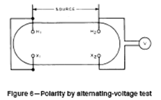
Any convenient value of alternating voltage shall be applied
to the full high-voltage winding and readings taken of the applied voltage and
the voltage between the right-hand adjacent high-voltage and low-voltage leads.
When the latter reading is greater than the former, the
polarity is additive. When the latter voltage reading is less than the former
(indicating the approximate difference in voltage between the high-voltage and
low-voltage windings), the polarity is subtractive.
Polarity by comparison
When a transformer of known polarity and of the same ratio
as the unit under test is available, the polarity can be checked by comparison,
as follows, similar to the comparison method used for the ratio test.
a) Connect the high-voltage windings of both transformers in
parallel by connecting similarly marked
leads together.
b) Connect the low-voltage leads, X2, of both transformers
together, leaving the X1 leads free.
c) With these connections, apply a reduced value of voltage
to the high-voltage windings and measure the voltage between the two free
leads.
A zero or negligible reading of the voltmeter will indicate
that the relative polarities of both transformers are identical.
An alternative method of checking the polarity is to
substitute a low-rated fuse or suitable lamps for the voltmeter. This procedure
is recommended as a precautionary measure before connecting the voltmeter.
Polarity by ratio bridge
The ratio bridge can also
be used to test polarity. A bridge using the basic circuit below may be used to
measure ratio.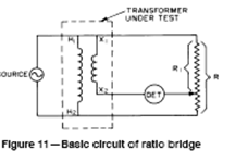
No comments:
Post a Comment