Below shows the voltage relations
across an autotransformer and switching contacts during a tap
changing cycle using an autotransformer designed for 60% circulating
current and with 100% load current at 80% power factor flowing
through it.
Perfect interlacing between the
autotransformer halves is assumed, and the voltage drop due to
resistance of the autotransformer winding is neglected.
A study of the figure will disclose the
fact that increasing the magnetizing reactance of the autotransformer
to reduce the circulating current will
1. Increase the voltage across the full
autotransformer winding
2. Increase the voltage to be ruptured
3. Introduce undue voltage fluctuations
in the line
Since B-4 and B-3 represent the
voltages appearing across the arcing contacts when the bridging
position is opened at A and B, the voltage rupturing duty will
increase with
1. Increase in voltage between adjacent
taps
2. Increase in load
3. Decrease in power factor of the load
4. Decrease in the magnetizing current
for which the autotransformer is designed
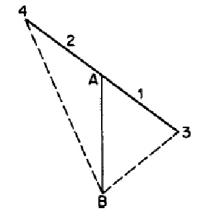
Vector relations for bridging position
AB—voltage across adjacent taps; A-1 and A-2— reactance volts due
to load current in only half the autotransformer winding; A-3 and
A-4—induced voltage across full auto transformer winding; B-4—
voltage ruptured when bridging position is ruptured
at A; B-3—voltage ruptured when
bridging position is ruptured at B.
No comments:
Post a Comment