This test determines the ratio (TTR) of
the number of turns in the high-voltage winding to that in the
low-voltage winding. The ratio test shall be made at rated or lower
voltage and rated or higher frequency.
In the case of three phase transformers
when each phase is independent and accessible, single phase power
should be used, although three-phase power may be used when
convenient. The tolerance for the ratio test is 0.5% of the winding
voltages specified on the transformer nameplate.
The accepted methods for performing the
ratio test are the voltmeter method, the comparison method, and the
ratio bridge. With the voltmeter method, the primary winding is
excited at rated frequency and the voltage at the primary and the
open-circuit voltage of the secondary winding are measured.
The ratio is the primary voltage
divided by the secondary voltage. The comparison method applies
voltage simultaneously to the transformer under test and the
open-circuit secondary voltages are measured and compared.
The ratio bridge method is the most
accurate method and can easily determine the TTR to the very small
tolerances required by the standard. The test apparatus is commonly
referred to as a TTR Test Set.
One such test set is manufactured by
the Biddle Company and has proven to be especially useful as a
diagnostic test in the field, so its operation will be described in
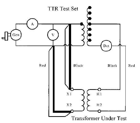
detail. This test set is shown in Figure 8.1.

FIGURE 8.1 Circuit diagram of a TTR test set.
The clamp test leads are connected to
the secondary winding of the transformer under test and the clip
leads are connected to the primary winding under test. The secondary
winding of the transformer under test and the secondary of a
calibrated reference transformer in the test set are both excited by
the same 8 V source voltage from a hand-cranked generator. A
voltmeter is used to verify that the correct voltage is being
applied.
An ammeter measures the exciting
current into the transformer under test. When the voltage developed
across the primary of the transformer under test (1-2) is equal to
the voltage developed across the primary of the calibrated reference
transformer (2-3), then the voltage across the synchronous rectifier
is zero and the galvanometer detector reads zero.
With more voltage developed across 1-2
than across 2-3, the galvanometer has a negative deflection. With
less voltage developed across 1-2 than across 2-3, the galvanometer
has a positive deflection. The ratio dials are used to adjust the
ratio of the reference transformer.
A simplified equivalent circuit of the
TTR test set is shown in Figure 8.2. The transformer under test is
also shown. Note that the current through the detector, labeled
‘‘Det’’ in the figure, is zero when the voltages developed at
the high-voltage terminals of the test-set transformer and the
transformer under test are equal. This condition exists when the
ratios of the test-set transformer and the transformer under test are
equal.
Its a great pleasure reading your post.Its full of information I am looking for and I love to post a comment that "The content of your post is awesome" Great work.
ReplyDelete