LOAD LOSSES OF POWER TRANSFORMERS BASIC INFORMATION
What Are The Load Losses Of Power Transformers?
The term load losses represents the losses in the transformer that result from the flow of load current in the windings. Load losses are composed of the following elements:
• Resistance losses as the current flows through the resistance of the conductors and leads
• Eddy losses caused by the leakage field. These are a function of the second power of the leakage field density and the second power of the conductor dimensions normal to the field.
• Stray losses: The leakage field exists in parts of the core, steel structural members, and tank walls. Losses and heating result in these steel parts.
Again, the leakage field caused by flow of the load current in the windings is involved, and the eddy and stray losses can be appreciable in large transformers. In order to reduce load loss, it is not sufficient to reduce the winding resistance by increasing the cross-section of the conductor, as eddy losses in the conductor will increase faster than joule heating losses decrease.
When the current is too great for a single conductor to be used for the winding without excessive eddy loss, a number of strands must be used in parallel. Because the parallel components are joined at the ends of the coil, steps must be taken to circumvent the induction of different EMFs (electromotive force) in the strands due to different loops of strands linking with the leakage flux, which would involve circulating currents and further loss.
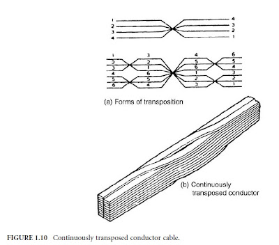
Different forms of conductor transposition have been devised for this purpose. Ideally, each conductor element should occupy every possible position in the array of strands such that all elements have the same resistance and the same induced EMF.
Conductor transposition, however, involves some sacrifice of winding space. If the winding depth is small, one transposition halfway through the winding is sufficient; or in the case of a two-layer winding, the transposition can be located at the junction of the layers.
Windings of greater depth need three or more transpositions. An example of a continuously transposed conductor (CTC) cable, shown in Figure 1.10, is widely used in the industry. CTC cables are manufactured using transposing machines and are usually paper-insulated as part of the transposing operation.
Stray losses can be a constraint on high-reactance designs. Losses can be controlled by using a combination of magnetic shunts and/or conducting shields to channel the flow of leakage flux external to the windings into low-loss paths.

No comments:
Post a Comment